Making a Car Spit….

Not literally… this is how I made a rotisserie to mount a car body so that it is easily rotated to any angle to make it easy to access the underside primarily for cleaning, repairing rust and painting without getting covered in muck.

1. Find some scrap 2″ square box section to make the end supports. Weld together as shown.

KONICA MINOLTA DIGITAL CAMERA

2. Fabricate the swivel/pivots bits. A short square section is where the shell will bolt onto the spit. A couple of offcuts of old galvanised iron pipe – approx 1 1/4″ diameter was used. I found some tube that they just about fitted in. A few minutes on the lathe to bore out the outer tubes to get a good fit.

KONICA MINOLTA DIGITAL CAMERA

3. Close up of the welds. It was all arc welded in my best joined up welding – it will carry quite a lot of weight so need to make sure its not going to snap!

KONICA MINOLTA DIGITAL CAMERA

4.  Leg 1 complete. The castors are heavy duty industrial ones with hard nylon wheels. I fitted one braked caster to each end.

KONICA MINOLTA DIGITAL CAMERA

5. Next is the inserts to the legs, this was some box section that slide quite nicely into the leg section. I then profiled the top to accept the pivot tubes.

KONICA MINOLTA DIGITAL CAMERA

6. Check the fit before welding!

KONICA MINOLTA DIGITAL CAMERA

7. Leg complete with insert. The insert can be raised or lowed to get the shell the right height.

KONICA MINOLTA DIGITAL CAMERA

8. Close up of the pivot.

KONICA MINOLTA DIGITAL CAMERA

9. Spindle mounted to a body shell – this shell is a 1955 Standard Eight I am supposed to be restoring.

KONICA MINOLTA DIGITAL CAMERA

10. Slightly in the wrong order but this pic shows the spindle welded onto the support bar.

KONICA MINOLTA DIGITAL CAMERA

11. A couple of brackets and a bit of angle were used to support the rear of the shell.

KONICA MINOLTA DIGITAL CAMERA

12. Dexion was used as an easily adjustable “interface” to the spit mount. Some trial and error is needed to get the mounting height correct so that the centre of gravity is in the middle – getting it right makes it easier to rotate the shell.

KONICA MINOLTA DIGITAL CAMERA

13.  Finshed Spit with shell mounted on it. There is a 2 1/2″round tube between the bottoms of the two support legs. All bolted together with M12 bolts.  Just a coat of Red paint need to make it look “professional”.

KONICA MINOLTA DIGITAL CAMERA

14. It works – put the shell at any angle!

KONICA MINOLTA DIGITAL CAMERA

15.  At this point I discovered a miscalculation in that the roof hits the tie bar. so I had to demount the body and lift up the mounting bars on the legs.

KONICA MINOLTA DIGITAL CAMERA

All in all a really useful bit of kit, should have made one years ago. The castors make it easy to move the shell around. When not needed the centre bar is unbolted and the whole lot occupies only a little space in the corner of the garage.

Let the welding begin……..rebirth of the AX


It gets worse before it gets better! I started on the worst looking bit, the front near side chassis leg where it runs down under the footwell. Basically I used a hammer and old 1″ wood chisel the remove the factory undrseal. This revealed the the full extent of the corrosion – so I thought! So I cut out the rusty metal with an angle grinder. I started removing the bottom of the chassis box section, I could then see inside. It was quite shocking to see that the sides had rotted as well – the rot was from the inside out – meaning that to the casual observer all looks OK.

KONICA MINOLTA DIGITAL CAMERA

This pic shows the extent of the rotten metal.

KONICA MINOLTA DIGITAL CAMERA


And another.

KONICA MINOLTA DIGITAL CAMERA


With the bad stuff gone, time to start a reconstruction – shame you can’t DIY 3D print steel yet! First bit was to build up the two sides of the box section.

KONICA MINOLTA DIGITAL CAMERA

Make a paper template and transfer this to the metal sheet. As this is a chassis section I’m using 1.2mm thick steel sheet. The sheet is a zinc coated one – trade name of this particular stuff is Zinctec. Basically a corrosion resistant weld through zinc finish – approx £18 for a 1m x 1m sheet. For body work and other non structural bits you can get away with 0.8mm thick.

KONICA MINOLTA DIGITAL CAMERA

Measure twice, cut once, goes the old adage. So before you cut the steel sheet double check your paper template is correct.

KONICA MINOLTA DIGITAL CAMERA

Steel sheet marked up ready to cut out. You can just about cut the steel with aviation snips but I use my bench sheers to rough out the section. Any bits that aren’t quite right I trim up with the angle grinder.

KONICA MINOLTA DIGITAL CAMERA

Got carried away and forgot to take some more pics. This shows both sides welded in. I’ll tidy the welds up later where required using the grinder. Note I have continuously welded all the joints rather than just spotting them.

KONICA MINOLTA DIGITAL CAMERA

Now I need to make a long strip and curve it roud to close up the box section.

KONICA MINOLTA DIGITAL CAMERA

Again I made a paper template. Before closing the box section off I sprayed the inside with Zinc rich weld through paint (I bought a few cans from Frosts when it was on offer a few weeks ago.) Really good stuff.

KONICA MINOLTA DIGITAL CAMERA

New piece ready to weld up, all edges carefully trimmed to fit well so its easy to butt weld all round.

KONICA MINOLTA DIGITAL CAMERA

As this is curved piece I started by tacking one end and tesing it round the curve and then tacking the other end when happy with the fit.

KONICA MINOLTA DIGITAL CAMERA

Getting there, one end fully welded.

KONICA MINOLTA DIGITAL CAMERA

Now welded all along one edge. Will roll the shell over on the spit to get a good angle on the other side. Note the welding is improving as I get into it again!

Next time finishing off the second layer.


Why did I Start This? – Full extent of rust revealed.

With the shell mounted on the spit it was wheeled outside and pressure washed so I could see how bad and how much rust there is.


KONICA MINOLTA DIGITAL CAMERA


Pressure washed, ready to look at

KONICA MINOLTA DIGITAL CAMERA


Front nearside chassis leg – common rot spot. The square hole was covered by a plastic cover under the underseal!

KONICA MINOLTA DIGITAL CAMERA

This is the worst bit the main chassis leg rotten right through – worryingly all hidden by the factory underseal.

KONICA MINOLTA DIGITAL CAMERA

Closer view!

KONICA MINOLTA DIGITAL CAMERA

Back end is better,

KONICA MINOLTA DIGITAL CAMERA

The rear is pretty solid, even the sills weren’t as bad as I first feared but will still need a lot of patching.


Spit Roast Citroen AX

The car is now stripped down, there is quite a lot of rust which needs cutting out and new metal welded in. As always most of this is on the more inaccessible underside. There is nothing worse than trying to clean up, cut out rust and weld up on the underside of a car. You end up covered in mud, paint, rust etc. and when it comes to welding it is hard to do a neat job whilst literally bending over backwards and looking up.  To overcome this a few years back I made a “rotisserie” or “car spit”. This is basically a cradle to which the car body is bolted, usually via the bumper mounting points – not on the AX though! – the cradle has pivots so the car body can be rotated. (not the best explanation so look at the pictures!).

1. The AX front bumper mounts are designed to crumple, deform and basically give up as soon as the car has a head on collision with a fly! So no chance of supporting the weight of the body on them. So I ended up drilling right through the front chassis legs, bolting on a spacer and a length of angle iron long enough to project forward past the bumper mounts. This gave two solid points to bolt another piece of angle between the two. This angle iron was then bolted to th front leg of the spit, The front of the car was lifted up on the gantry to the correct height to enable the spindle on the spit to locate with the leg.

KONICA MINOLTA DIGITAL CAMERA

KONICA MINOLTA DIGITAL CAMERA


All ready to lift up onto the front leg of the spit

KONICA MINOLTA DIGITAL CAMERA


Note the big “washers” to spread the load on the inside of the chassis leg

2. All lifted up, front end no engaged!

KONICA MINOLTA DIGITAL CAMERA

3. The back end was then fixed to the rear leg. This was a lot easier as the cross beam just bolted to the rear bumper mounts which are a lot less “wafty” than the front ones.

KONICA MINOLTA DIGITAL CAMERA

4. Pic of the rear end (car is mow on its side!

KONICA MINOLTA DIGITAL CAMERA

5. Pic. of the front end (car still on its side.

KONICA MINOLTA DIGITAL CAMERA

6. Final pic.

KONICA MINOLTA DIGITAL CAMERA

7. The car car be moved to what ever angle I want. I might adjust the mounting height as the car is a bit top heavy at the moment. The legs are adjustable and I can lift the whole car higher so that it will rotate all the way round. The spit is also on castors so it is easy to wheel the body around to give lots or room where you are working.


It took about half a day to mount the body on the spit – worth the effort in my opinion as it will make it so much easier and quicker to clean and weld up.


Next time – the welding begins……..

Citroen AX – Stripdown – The Final Bit

Last few bits – Fuel tank, pipes and front struts and wishbones.

Lets start with the fuel tank.

1. Remove the filler cap and undo the 2 torx screws to release the filler tube.

KONICA MINOLTA DIGITAL CAMERA

2. In the wheel arch there is a large plastic retainer which holds the bottom of the filler tube in place, this simply unscrews.

KONICA MINOLTA DIGITAL CAMERA

3. This shows the plastic retainer removed.

KONICA MINOLTA DIGITAL CAMERA

4. Now support the tank before going any further, If it still has fuel in it it could be heavy! Then undo the two retaining nuts and remove the rubber pads.

KONICA MINOLTA DIGITAL CAMERA

5. Nuts removed.

KONICA MINOLTA DIGITAL CAMERA

6. Up top remove the two fuel pipes and the wiring loom. The pipes may be difficult due to restricted access so just release the clips at this stage.

KONICA MINOLTA DIGITAL CAMERA

7. Not necessary but you can remove the heatsheild. It is held on by 3 plastic “rivets”

KONICA MINOLTA DIGITAL CAMERA

8. Now you can start to lower the tank (or lift the body up), Ensure you ease the filler pipes over the lip at the end of the sill.

KONICA MINOLTA DIGITAL CAMERA

9. This pic shows the tank starting to come away. There rear edge comes down and when it is clear of the studs it can be pulled back to release the front edge.

KONICA MINOLTA DIGITAL CAMERA

10. On the way down you need to put your hands over the front of the tank to reach up and release the two fuel pipes. There is a push in clip locating the pipes towards the passenger side. Follow the pipes along and you can feel it. Once removed, feed the pipes and wiring loom through the grommets and into the sill. Then inside the car pull the pipes and wire through the sill so that they are away from any danger of getting damaged during the welding of the sill.

KONICA MINOLTA DIGITAL CAMERA

11. Finally remove the wishbones and struts. The wishbones are held on by the rear bracket which is attached to the floorpan via nuts accessed through a flap in the bulkhead sound deadening mat at the front of the foot well. Next undo and remove the front nut and bolt from the wishbone. Remove the two bolts securing the caliper tot he strut, release the trackrod end (1 nut), finally undo the two nuts at the top of the strut, hold the strut as you do this as it will drop down. The whole assembly can now be lifted off

KONICA MINOLTA DIGITAL CAMERA

12. And there we have it – one shell ready to weld – I didn’t remove the windscreen, dash or headlining, or the steering rack and master cylinder.

KONICA MINOLTA DIGITAL CAMERA


Next time mounting the shell on a “rotissery” so that I can “get at” the shell when welding.


Citroen AX – The Stripping Continues…….

Ok so I’m getting carried away here now but as I’ve got so far might as well get it down to pretty much a bare shell, will make it easier to cut out the rotten bits and weld it up again – tonights stripping removed the handbrake and gear lever, rear bumper, rear loom, tail gate catch, spare wheel carrier and finally the rear beam.

1.  First remove all the plastic blanking plugs – two big black ones over the diesel tank and four smaller white ones covering the rear beam mounting bolts.

KONICA MINOLTA DIGITAL CAMERA

2. On petrol AX’s one hole has the fuel pump and the other the fuel gauge sender unit. On the diesel the pump is on the engine so there is nothing under one of the blanking plugs. This picture shows the flow and return pipes and the loom connecting to the sender unit.

KONICA MINOLTA DIGITAL CAMERA

3. This shows the passenger side front rearbeam mounting hole, also the wiring loom that runs to the rear of the car removed and also the fuel pipes which will have to be removed to allow the rear of the sill to be welded.

KONICA MINOLTA DIGITAL CAMERA

4.  This is the spare wheel carrier removed, simply completely undo the retaining bolt and then unhook the carrier.

KONICA MINOLTA DIGITAL CAMERA

5. Most of the bolts at the rear end were pretty corroded so a quick squirt of penetrating oil on all the bolts and also the brake unions before proceeding further should make things easier.

KONICA MINOLTA DIGITAL CAMERA

6. More squirts! (and an errant rubber exhaust hanger)

KONICA MINOLTA DIGITAL CAMERA

7. Whilst waiting for thepenetrating oil to do its magic remove the gear lever.

KONICA MINOLTA DIGITAL CAMERA

8. Inside the car undo the four M10 nuts around the gear lever.

KONICA MINOLTA DIGITAL CAMERA

9. Lever removed and also large patch of rust.

KONICA MINOLTA DIGITAL CAMERA

10. Next the handbrake, the cables need to be unhooked. Usually you slacken off the adjusters at the back of the brake drums, in this case being lazy I unbolted the lever to enable it to be moved back enough to be able to unhook the cables.

KONICA MINOLTA DIGITAL CAMERA

11. From above undo the two 13mm bolts.

KONICA MINOLTA DIGITAL CAMERA

12. And lift out the lever after disconnecting the cables from below.

KONICA MINOLTA DIGITAL CAMERA

13. Handbrake removed. Now go underneath and unclip the handbrake cables all the way back to the rear brake drums.

KONICA MINOLTA DIGITAL CAMERA

14. Now onto the rear bumper, first remove the two 10mm nuts underneath.

KONICA MINOLTA DIGITAL CAMERA

15. On top lift out the three black plastic “rivets”

KONICA MINOLTA DIGITAL CAMERA

16. Picture shows centre and left hand plastic fixings.

KONICA MINOLTA DIGITAL CAMERA

17. Finally at either end of the bumper underneath releasethe clips, the bumper “cover” will then simply slide back.

KONICA MINOLTA DIGITAL CAMERA

18. This shows the plastic bracket on the shell.

KONICA MINOLTA DIGITAL CAMERA

19. This is the bumper itself, held on by two 10mm nuts. Undo the nuts and remove.

KONICA MINOLTA DIGITAL CAMERA

20. Bumper removed, at the sameime unclip the wiring loom running from side to side.

KONICA MINOLTA DIGITAL CAMERA

21.  Remove the earth wire.

KONICA MINOLTA DIGITAL CAMERA

22.  Pull off the two plastic edge covers in the tail light apertures.

KONICA MINOLTA DIGITAL CAMERA

23. Gone!

KONICA MINOLTA DIGITAL CAMERA

24. Remove the tailgate catch, undo the two 10mm bolts.

KONICA MINOLTA DIGITAL CAMERA

25. Lastly we are removing the rear beam (or axle). To do this you need to lift the back end of the car.

KONICA MINOLTA DIGITAL CAMERA

26. Before starting to lift, disconnect the brake pipes from the hoses – watch out as the fluid will escape so be prepared to catch it. I’m replacing all pipes and hoses so the system will be drained anyway. Then undo the four large nuts from above. If you are lucky the nuts will undo without the bolts rotating. If not then you will need a helper to hold a spanner below, or you need to wedge a spanner above and undo the bolts from below. Beware as the front of the beam will drop down so it is wise to support this with an axle stand under the shock absorber mounting.

KONICA MINOLTA DIGITAL CAMERA

27. Now lift the back end right up and the axle will be free. Lift the body high enough so that the rear axle can be rolled out on the wheels.

KONICA MINOLTA DIGITAL CAMERA

28. Bare bottom!  Back end stripped and free of clutter ready to clean up and have the rusty bits repaired.

KONICA MINOLTA DIGITAL CAMERA

29. Rear Beam and bumper removed.

KONICA MINOLTA DIGITAL CAMERA

Next time – removing the last bits at the front – oh and also the fuel tank!

2015 Eclipse – non event in the south east

20th March 2015. Yet again in the south east cloud cover removed any chance of seeing an astronomical (is that the right term?) event. However, the weather station did record a small but significant temperature drop at the time of the eclipse. The graph below shows a drop of around 0.5 degrees Celsius. Look at the green line on the bottom graph. Not much change in the windspeed though, it was said that during the eclipse the windspeed drops, but this time I can see no evidence here.

eclipse temperature


Citroen AX – The Rust – in the most surprising places!

Having stripped the interior I could have a good look at the extent of the rust.

1. Drivers side inner sill. Where the floorpan meets the sill.

KONICA MINOLTA DIGITAL CAMERA

2. This patch is on the inside beside the gear lever!  It is quite bad – how?????

KONICA MINOLTA DIGITAL CAMERA

3. This is looking into the rear of the sill on the drivers side. Not too bad, it looks worse on the outside.

KONICA MINOLTA DIGITAL CAMERA

4. And another close up.

KONICA MINOLTA DIGITAL CAMERA

5. Can’t remember where this is!!!

KONICA MINOLTA DIGITAL CAMERA

6. Drivers side rear inner arch – behind rear wheel.

KONICA MINOLTA DIGITAL CAMERA

7. Same on the passenger side.

KONICA MINOLTA DIGITAL CAMERA

8. Another mystery rot area, this is along the bottom of the passenger side rear quarter window, really very rotten in two small areas, worse on the inside!

KONICA MINOLTA DIGITAL CAMERA

9. Same area from outside.

KONICA MINOLTA DIGITAL CAMERA

10. Passenger side inside sill at the rear end.

KONICA MINOLTA DIGITAL CAMERA

11. Front floor pan passenger side.

KONICA MINOLTA DIGITAL CAMERA

12. Another two “funny” spots, above the passenger side front wishbone mountings. The mountings themselves are rust free – not to be confused with free rust.

KONICA MINOLTA DIGITAL CAMERA

More pics of the underside later. So far it all looks striaght forward, the insides of the sills are not as bad as first feared.

Citroen AX – Strip Down!

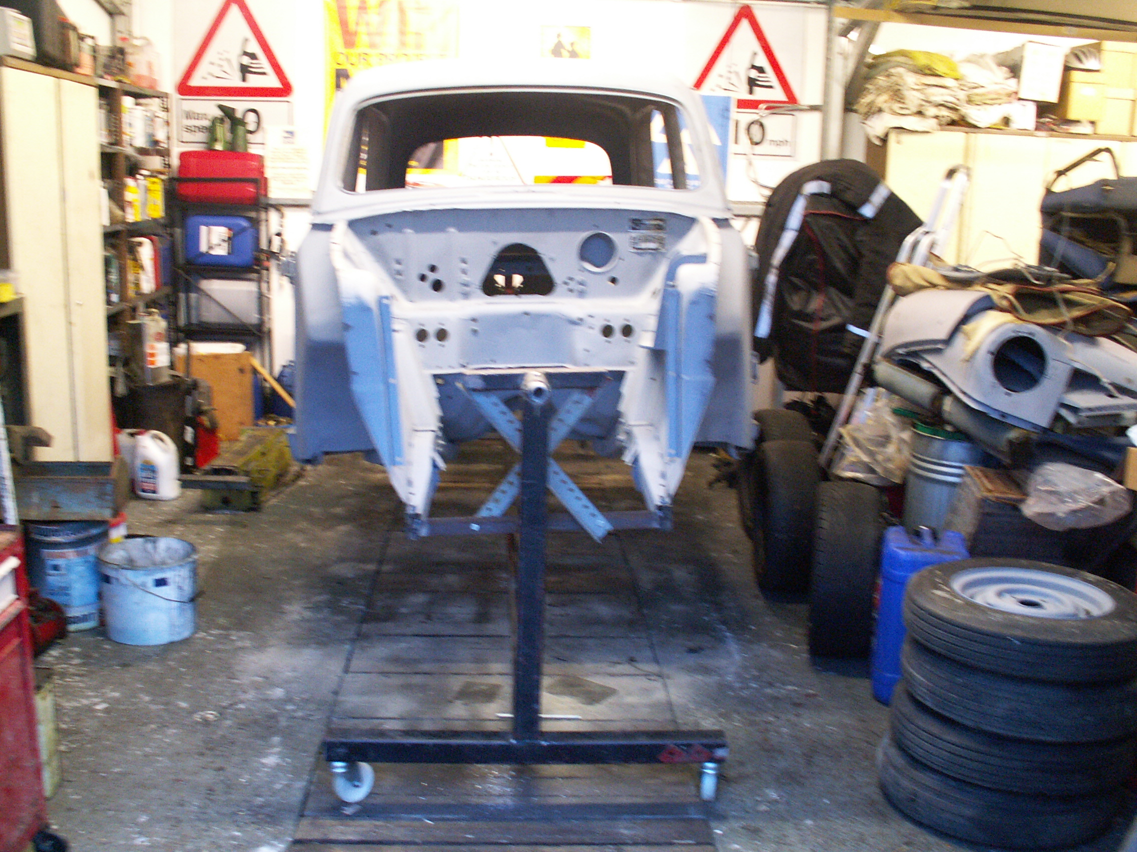
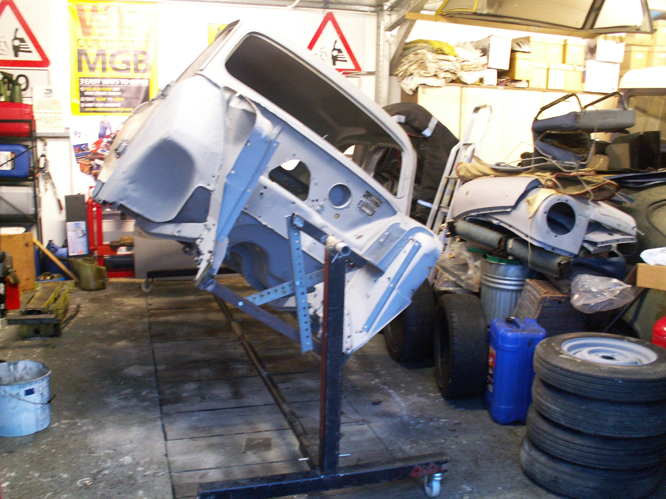
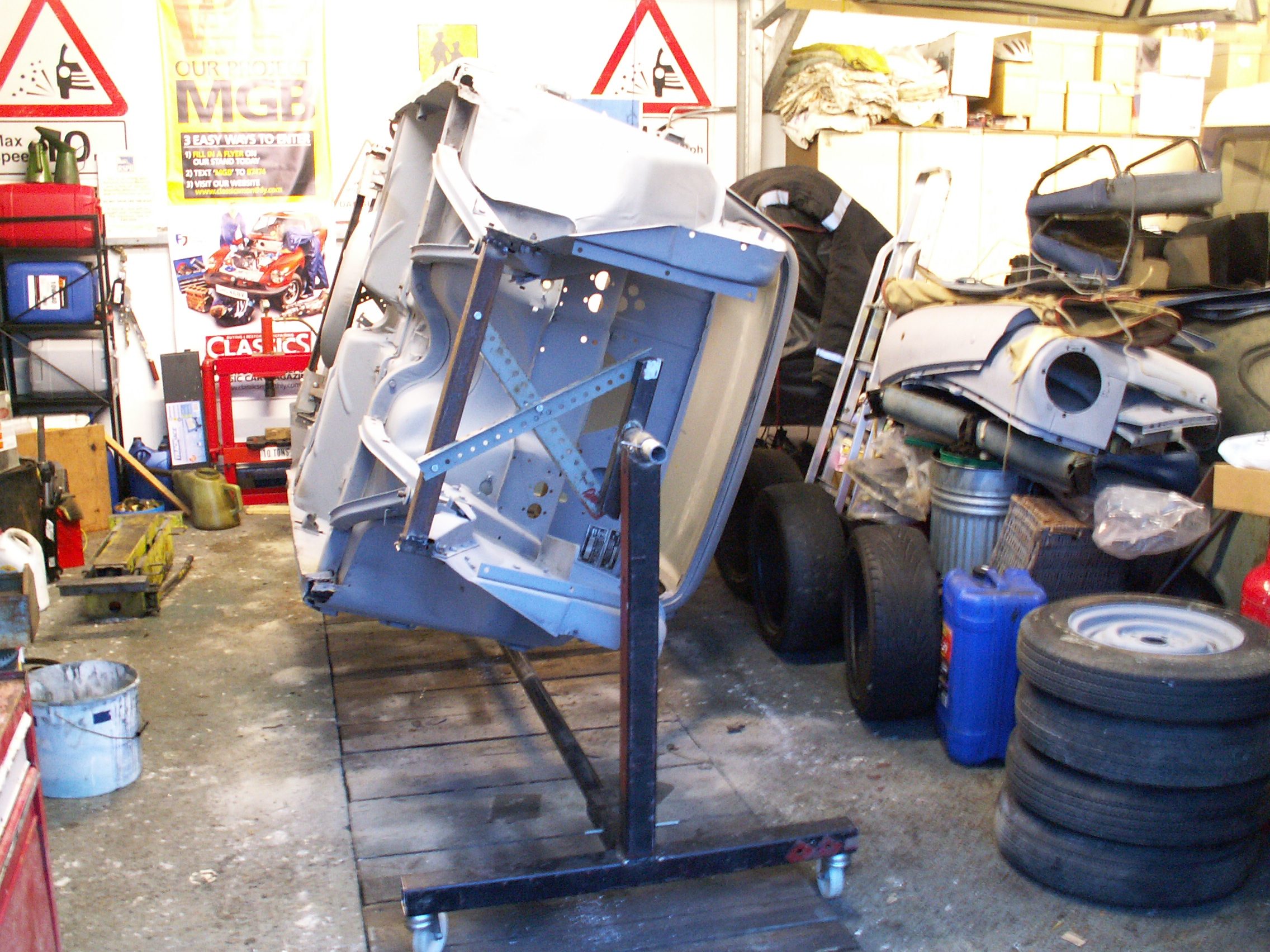
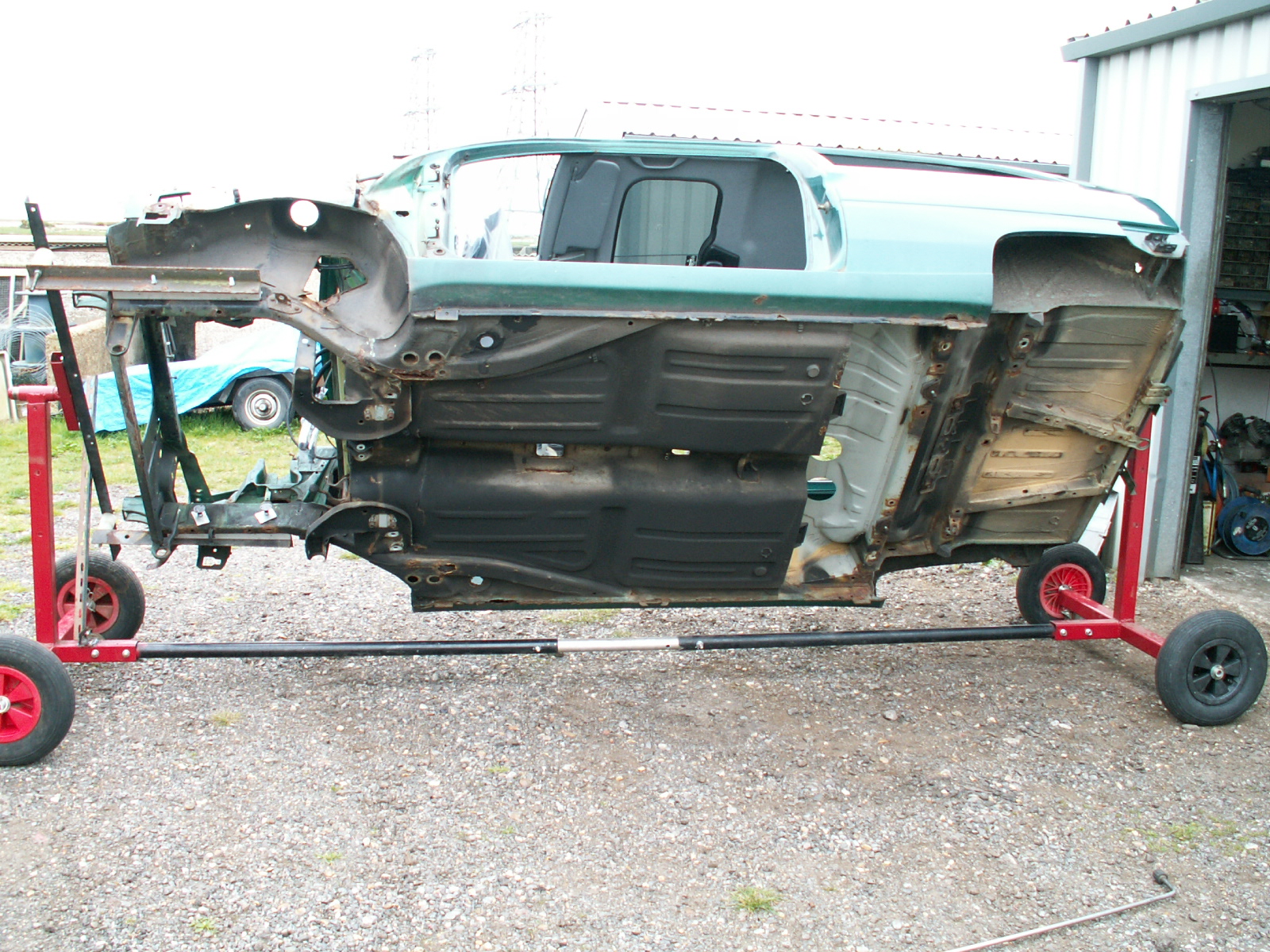
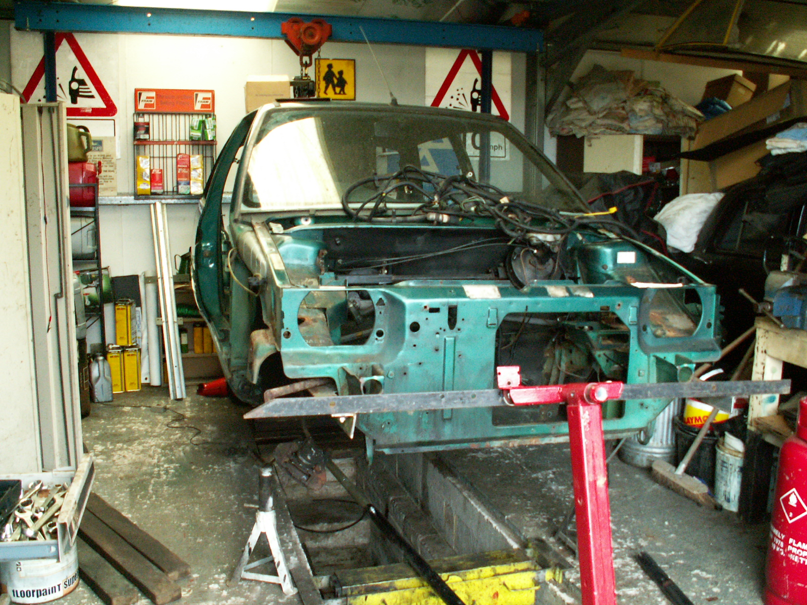
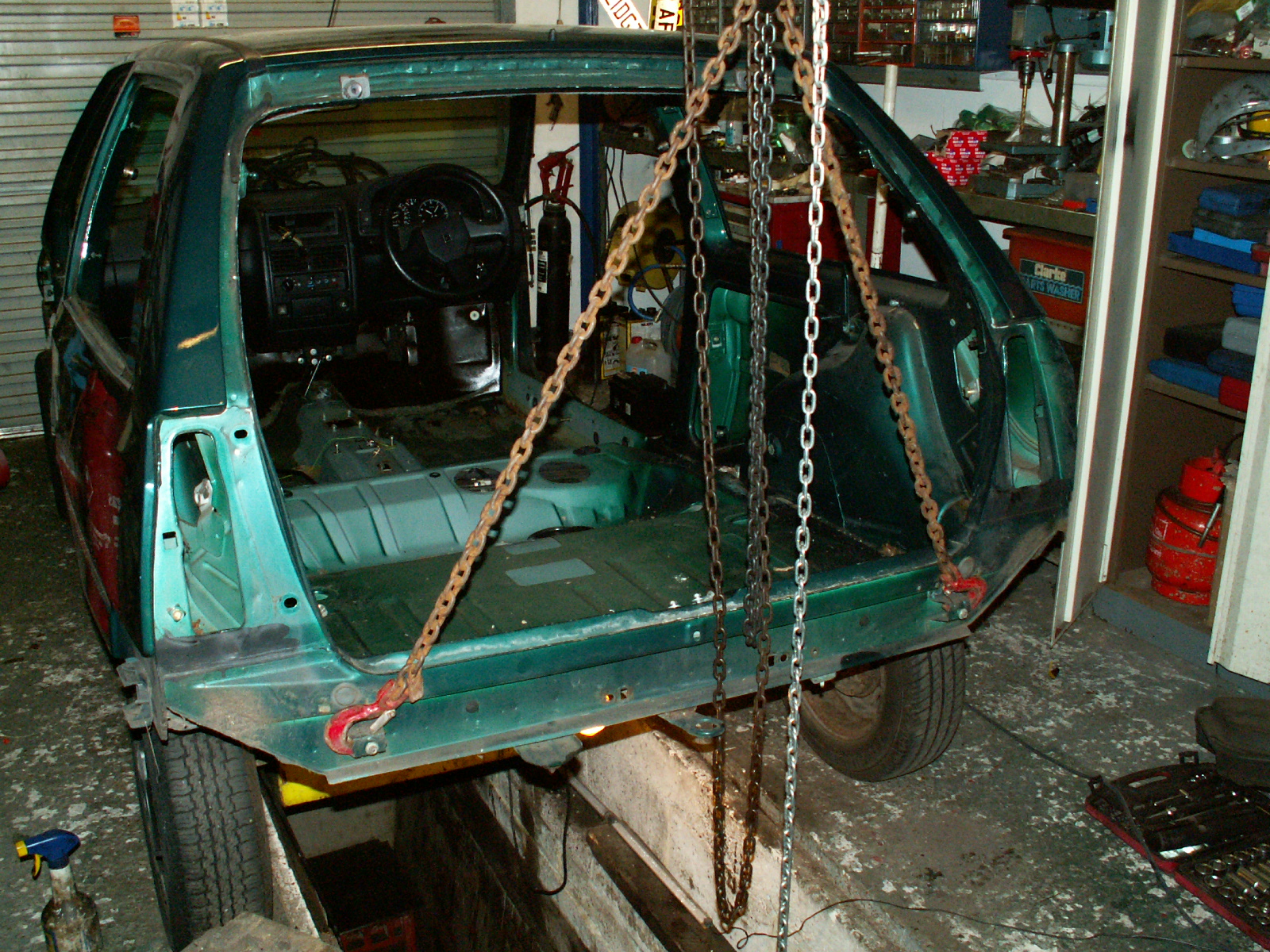
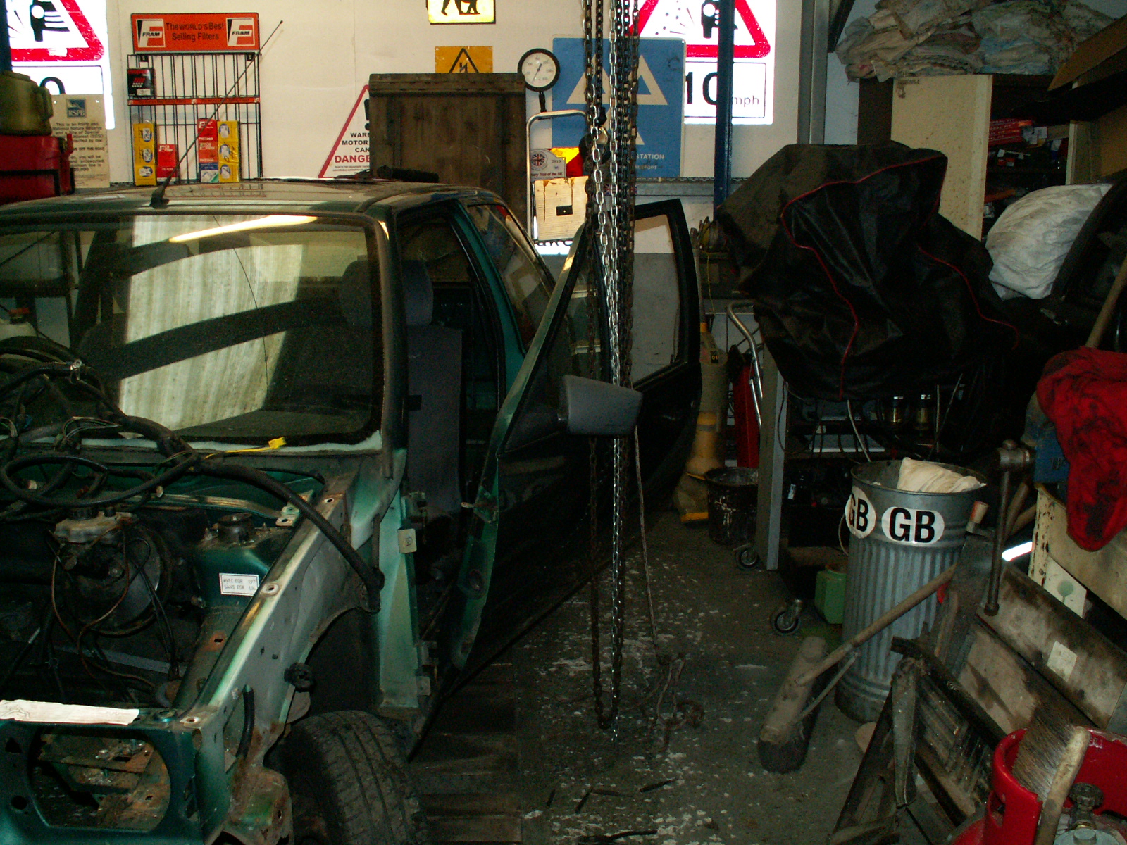
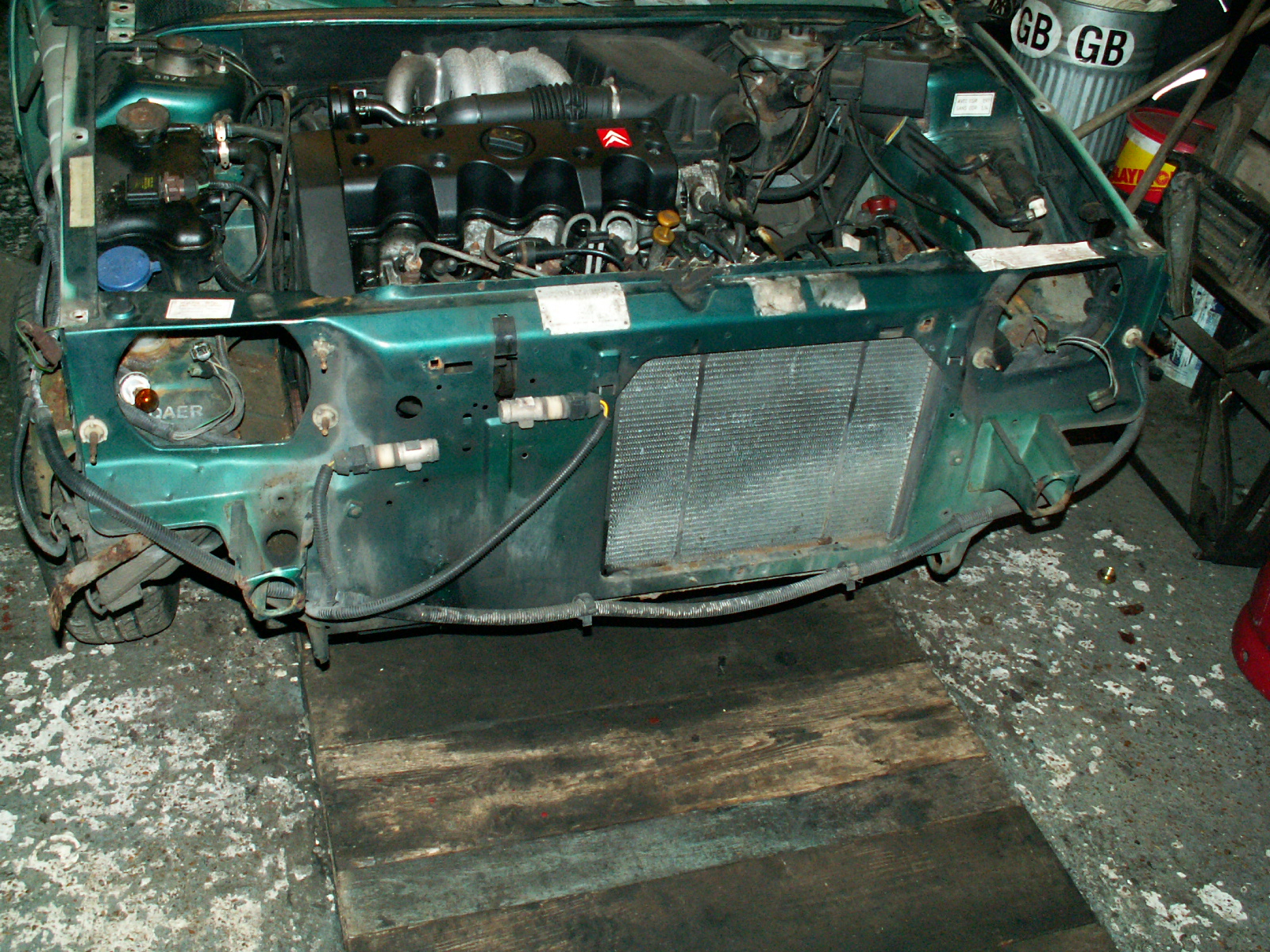
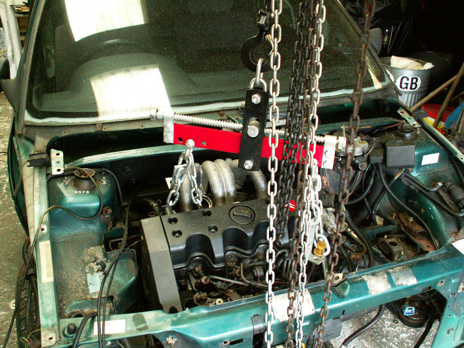
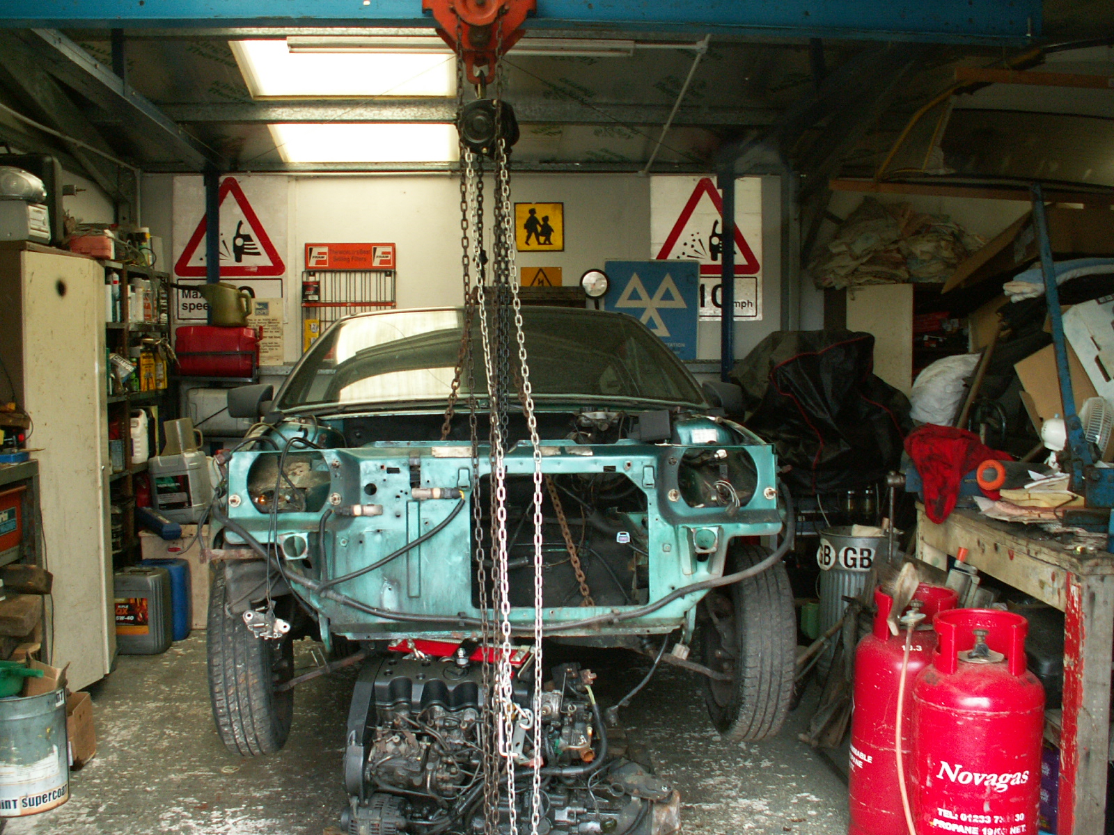
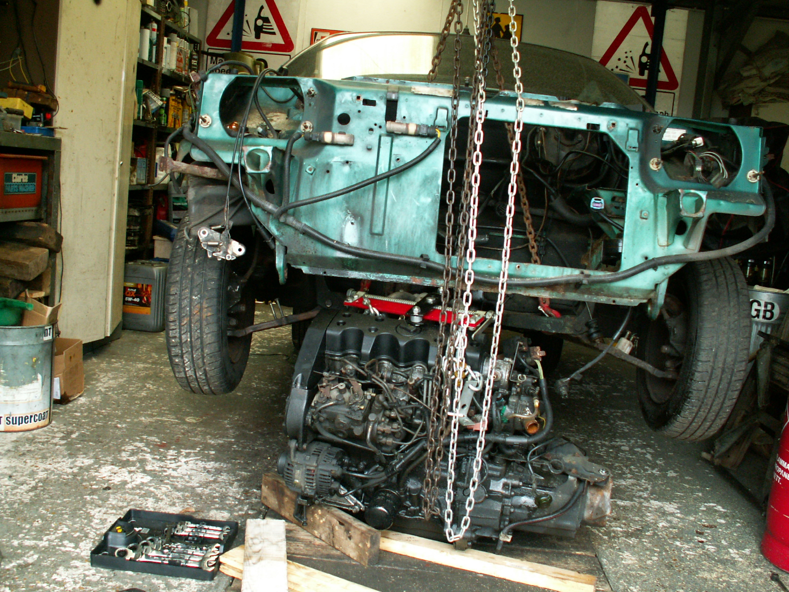
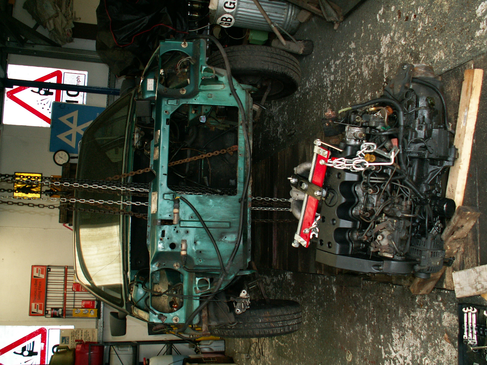
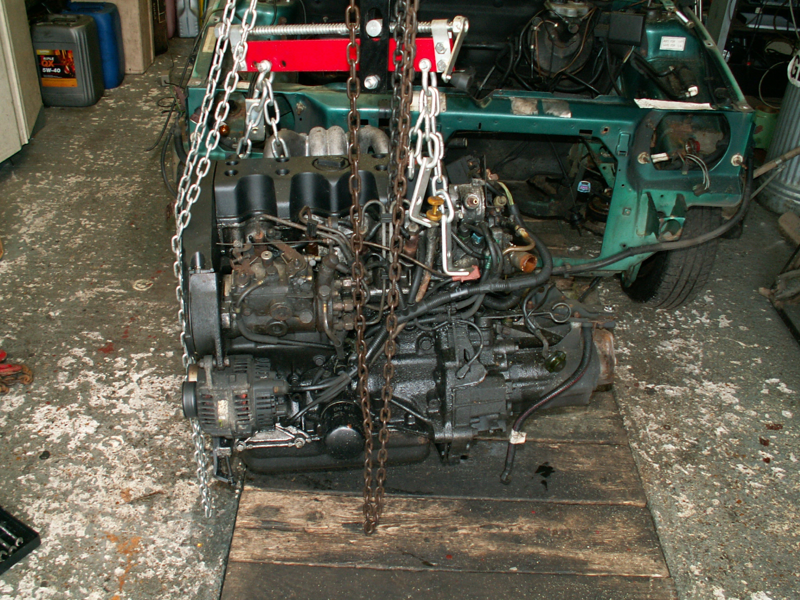
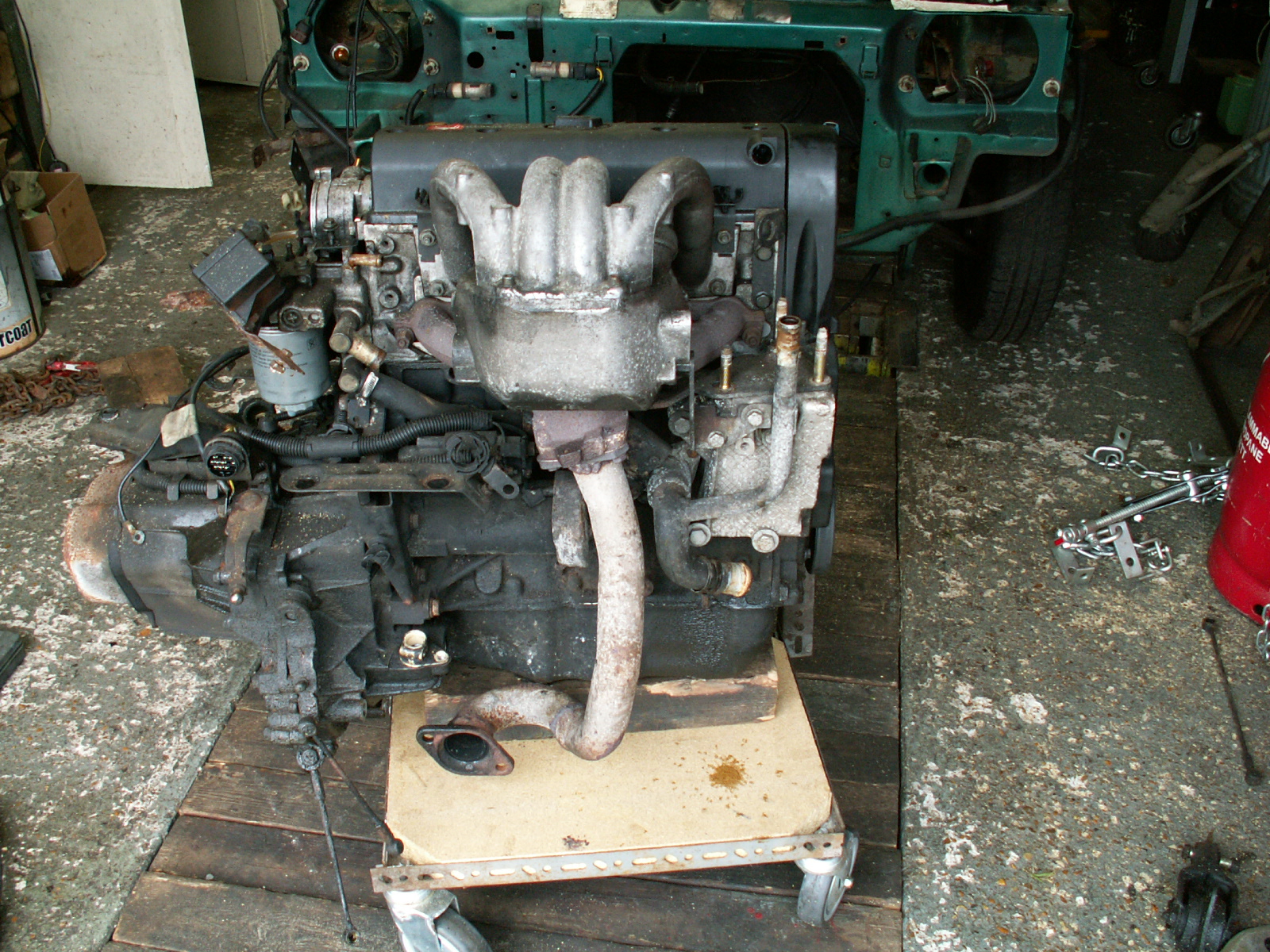
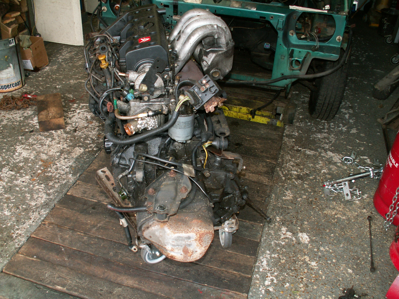
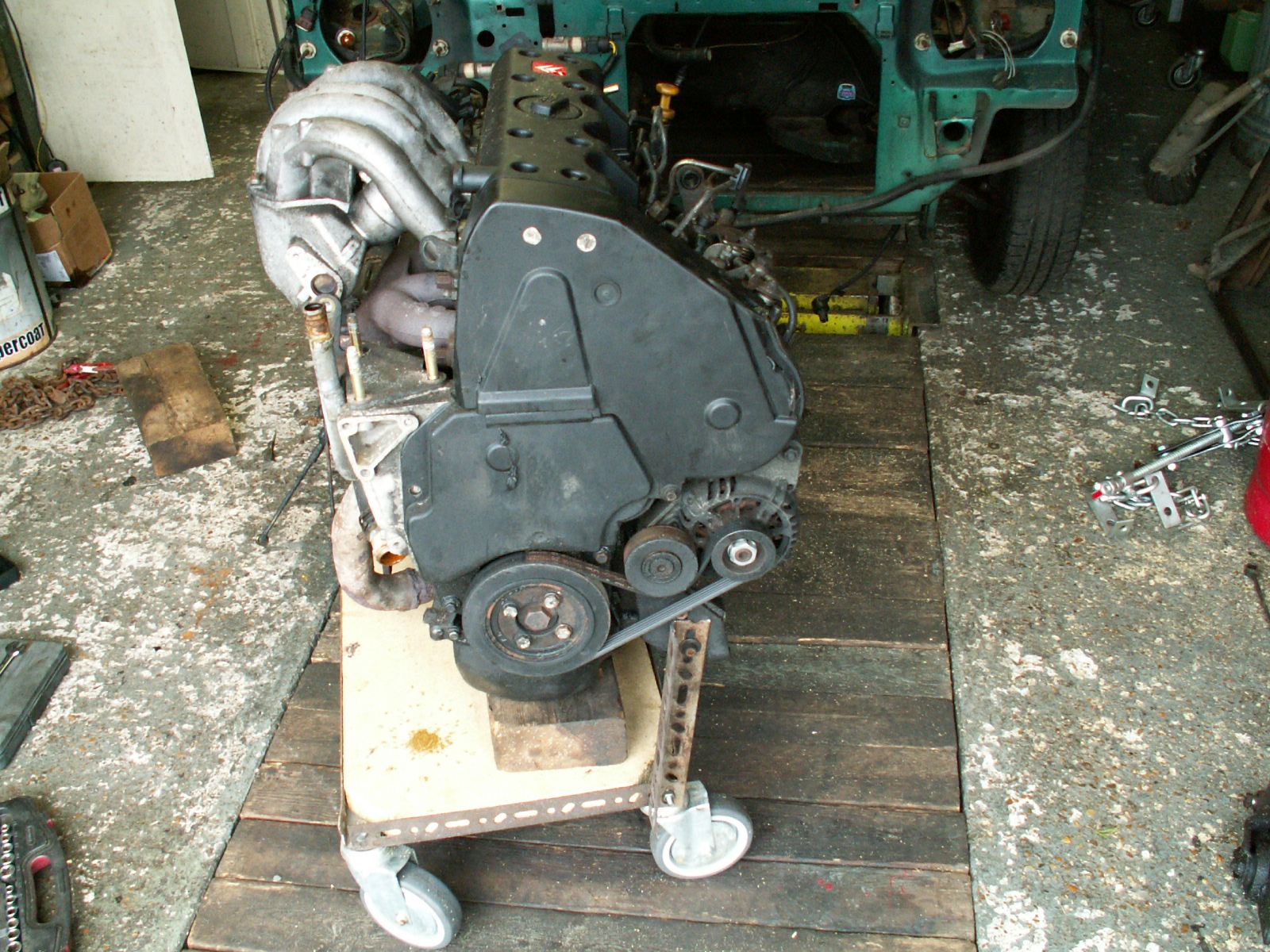
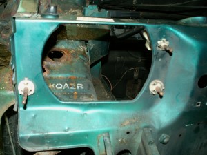
Having removed the engine I then got carried away and decided to strip the rest of the car back to a bare shell so I could get at all the rust. So what started as a quick resurrection of a cheap and economical run around has turned (inevitably!) into pretty much a full restoration!

1.  Start at the drivers side front, remove the remaining wiring and the washer tubing to the windscreen.

KONICA MINOLTA DIGITAL CAMERA

2. Remove the washer bottle, warm the washer tubing going to the rear screen with a heat gun to make it easy to remove from the pump.

KONICA MINOLTA DIGITAL CAMERA

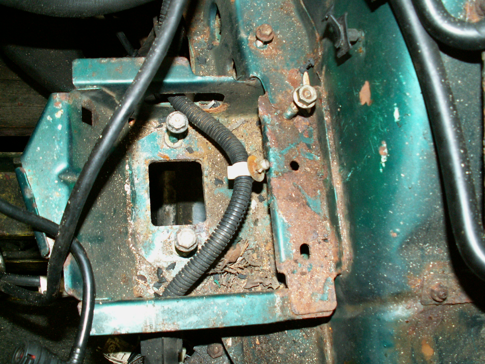
3. Undo the M10 bolt on the rear of the slam panel which acts as the earthing point for the drivers side lights.

KONICA MINOLTA DIGITAL CAMERA

4. Nearly all clear this side.

KONICA MINOLTA DIGITAL CAMERA

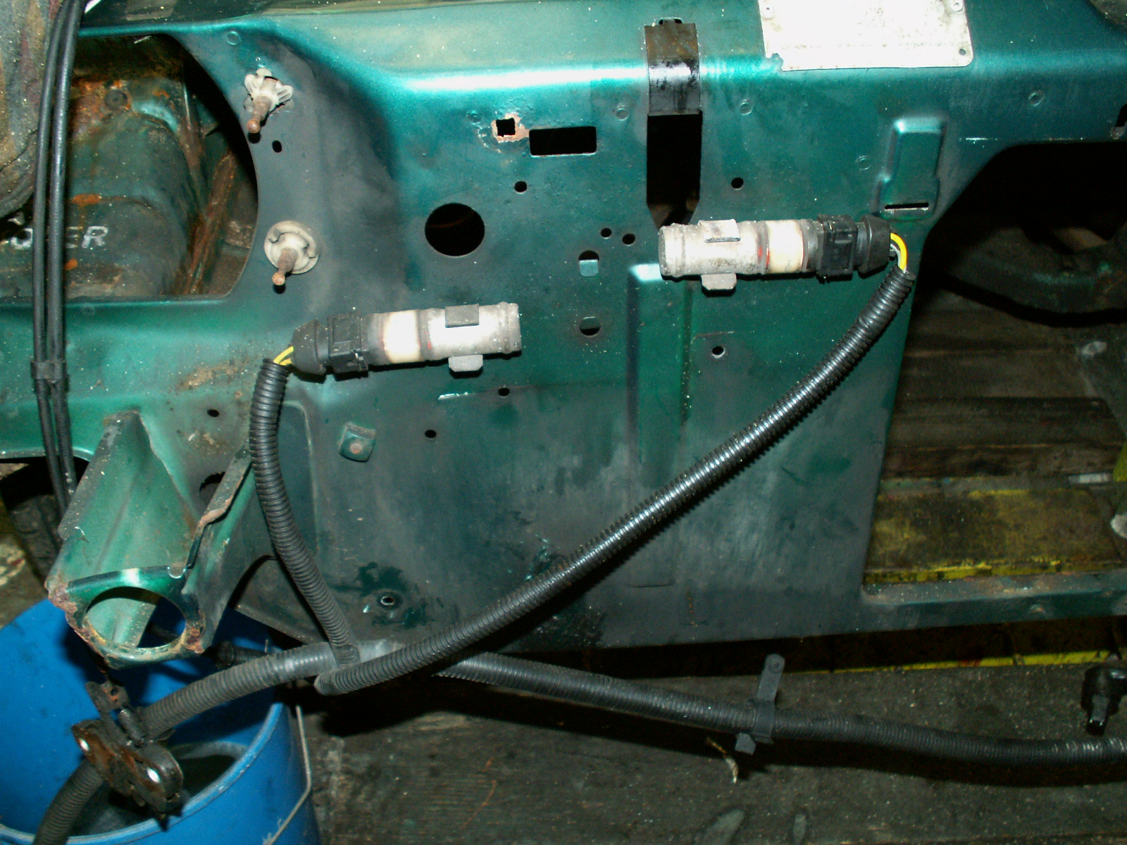
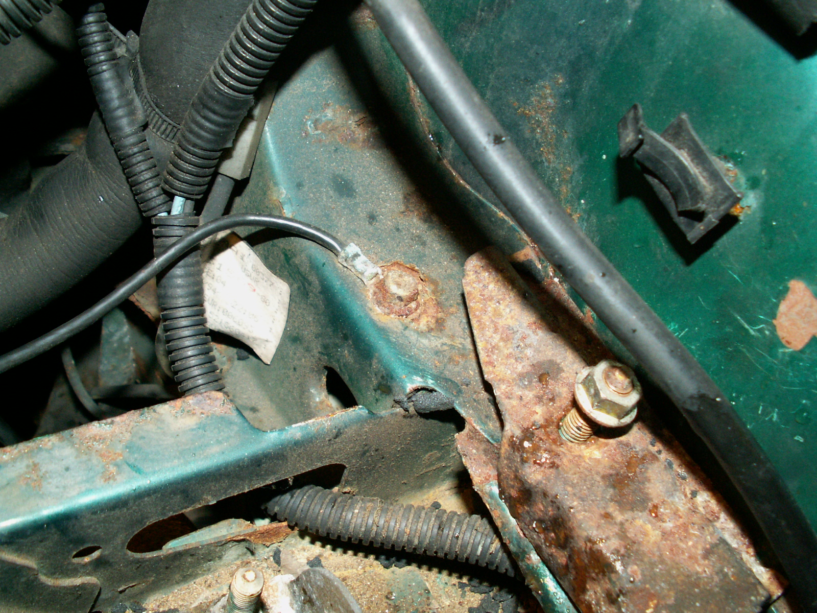
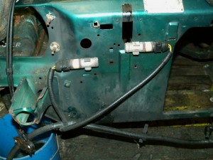
5.  Now work along the front of the car, unclip the inertia sensors from the front of the slam panel, also remove the metal clips. Not sure why there are two of them!

KONICA MINOLTA DIGITAL CAMERA

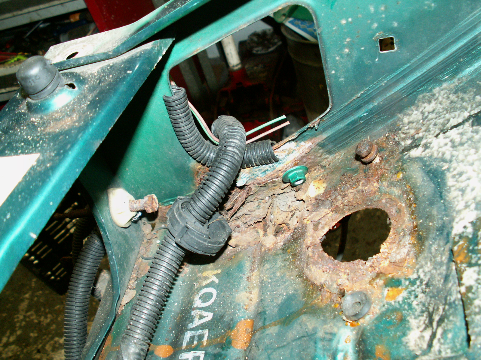
6. Now on to the passenger side. Remove the brown pad warming wire.

KONICA MINOLTA DIGITAL CAMERA

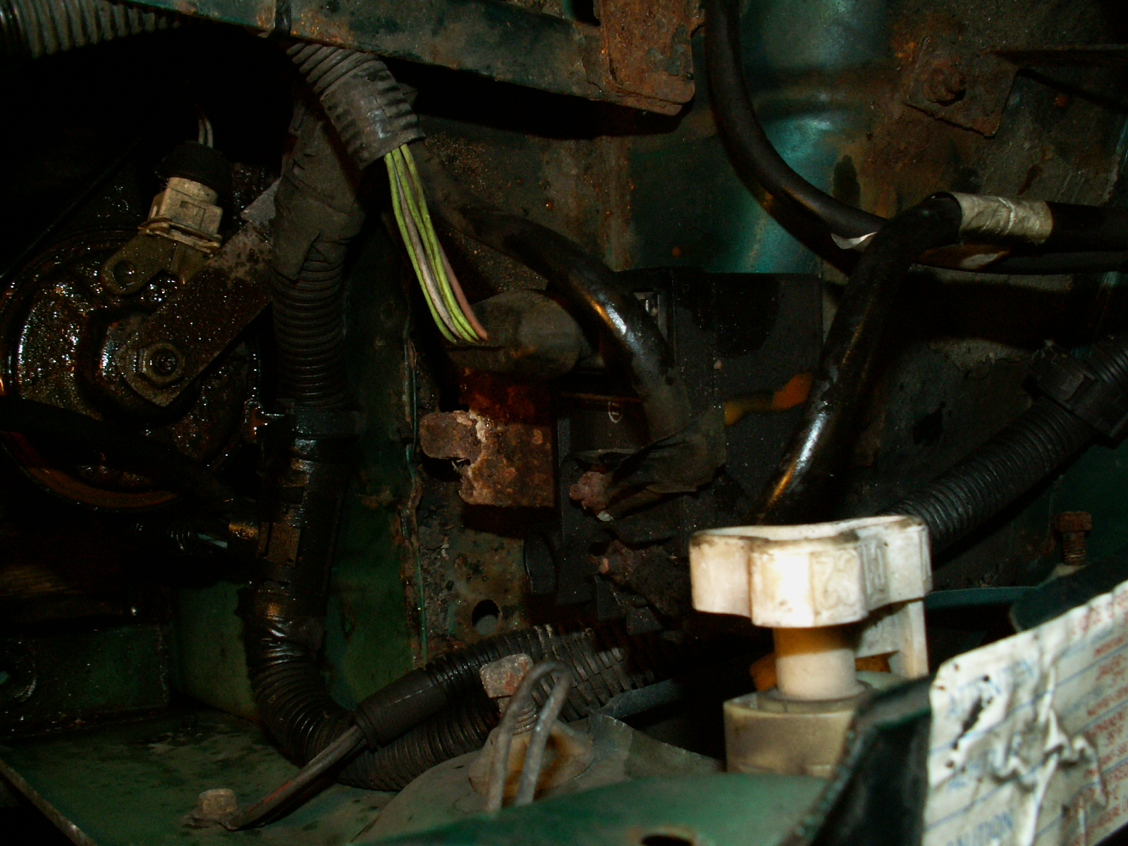
7. Unclip the wiring loom where it goes through the battery tray.

KONICA MINOLTA DIGITAL CAMERA

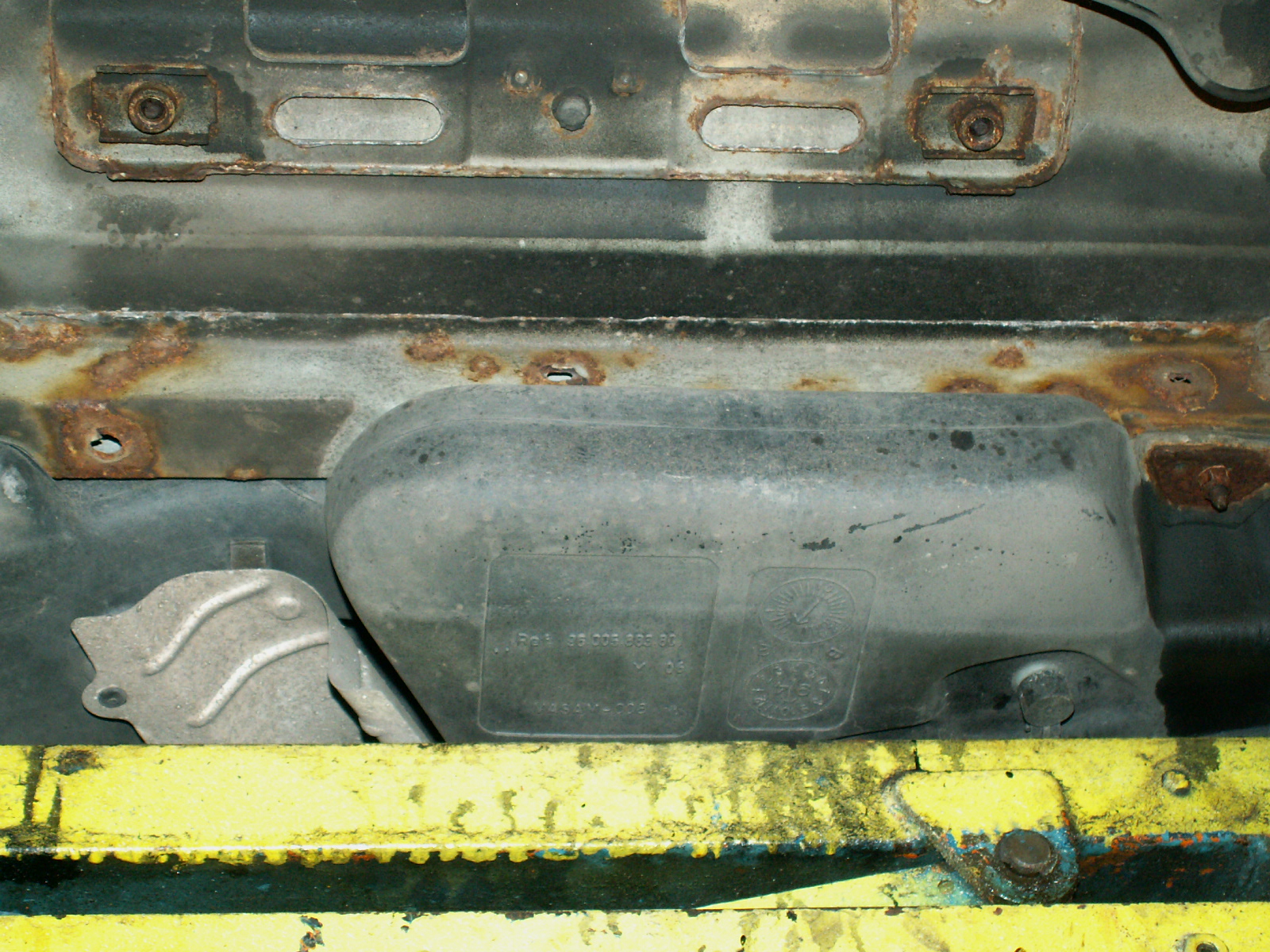
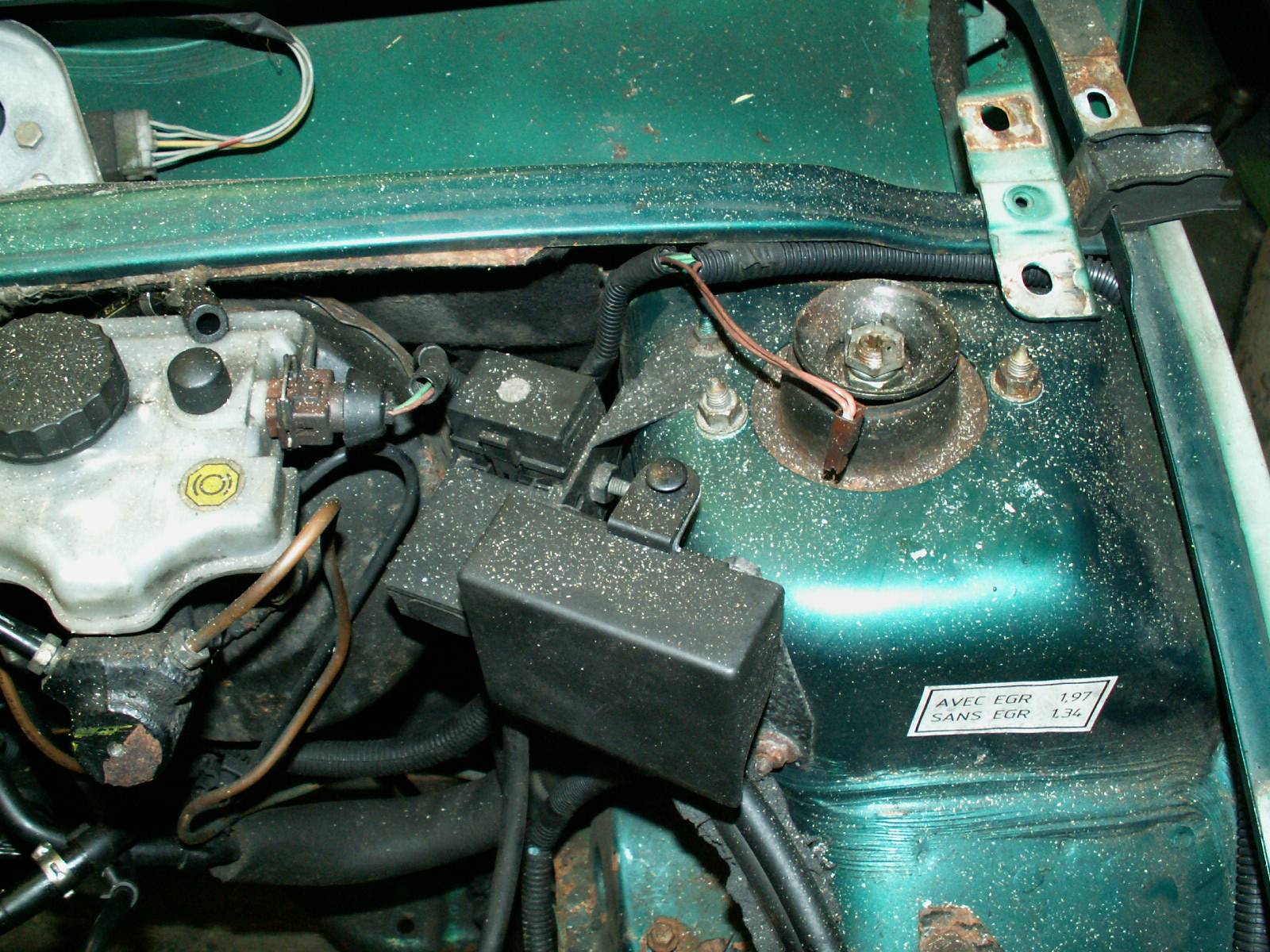
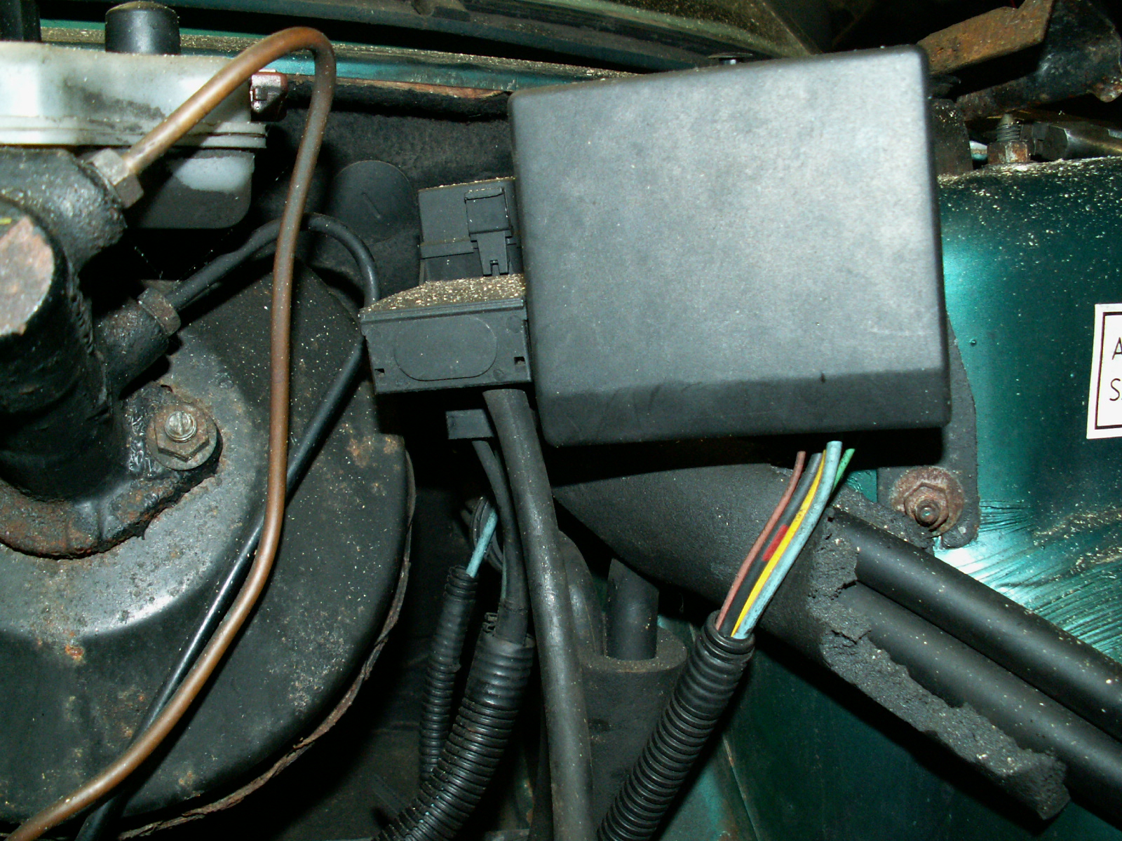
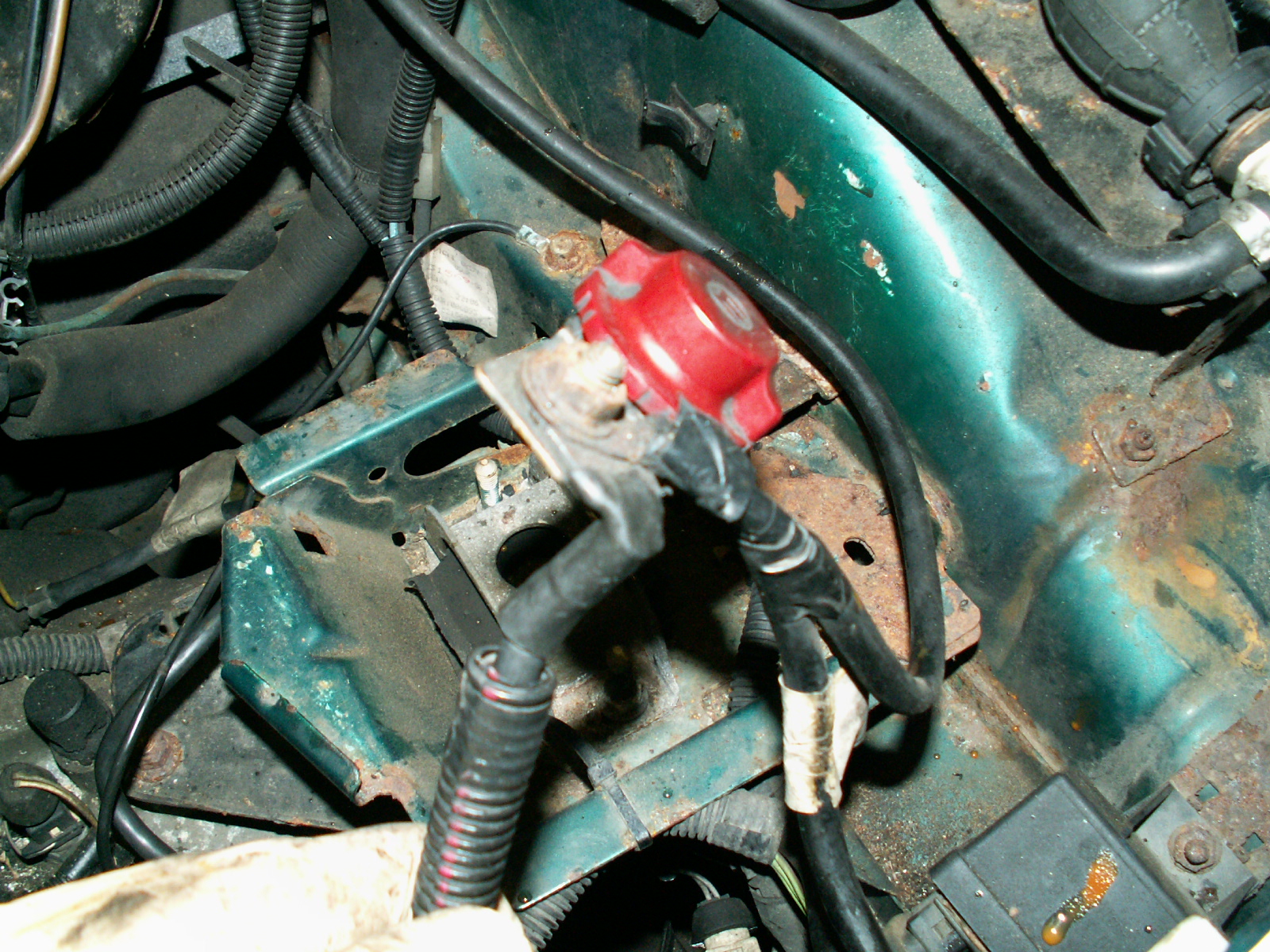
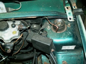
8. Next the junction boxes – I took more pictures so I can see how they went when it comes to reassembly.

KONICA MINOLTA DIGITAL CAMERA

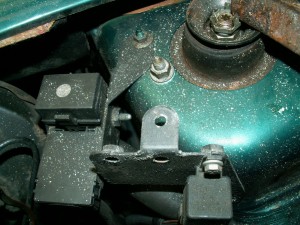
9. This shows the cover removed.

KONICA MINOLTA DIGITAL CAMERA

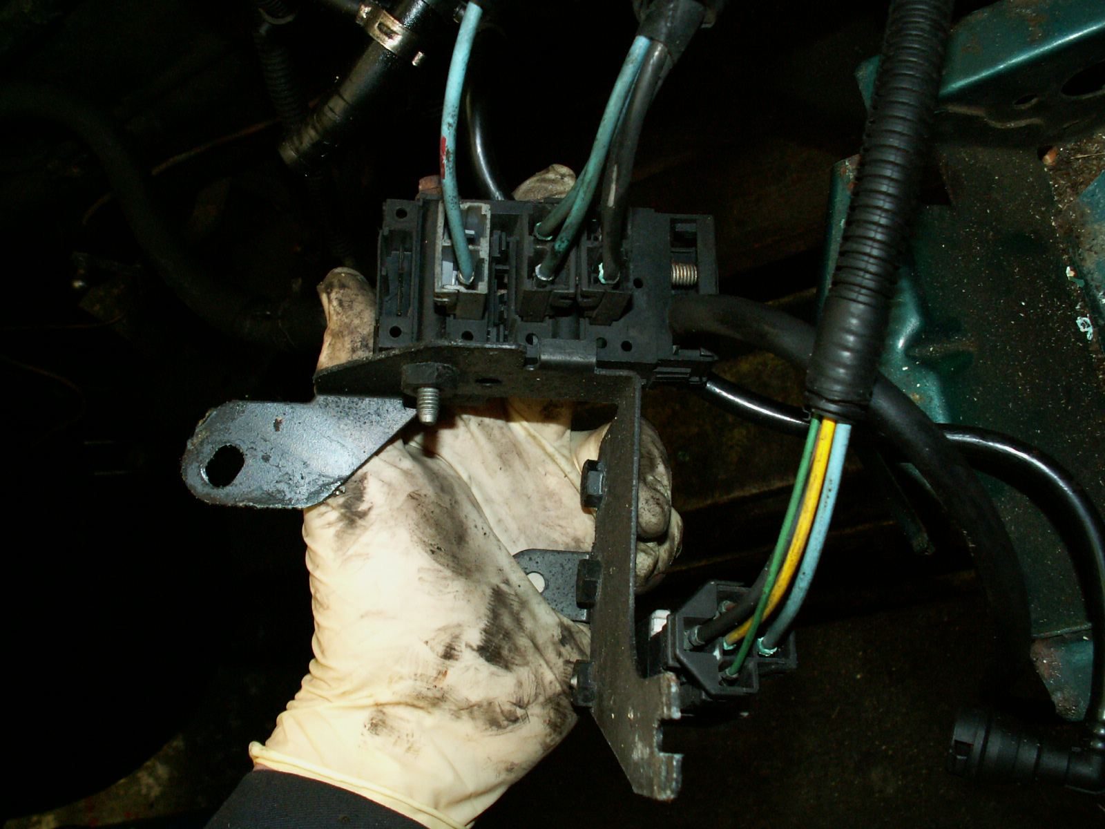
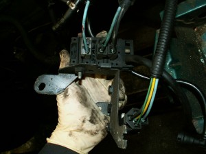
10. After unbolting the junction boxes unplug the three cables – note the order, the connectors do not appear to be keyed!

KONICA MINOLTA DIGITAL CAMERA

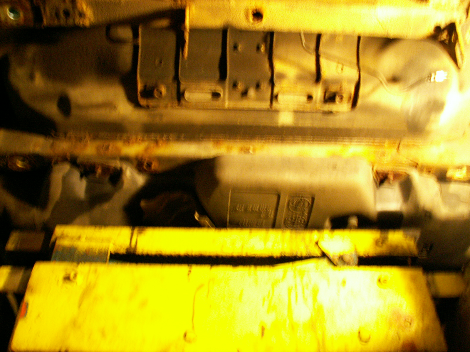
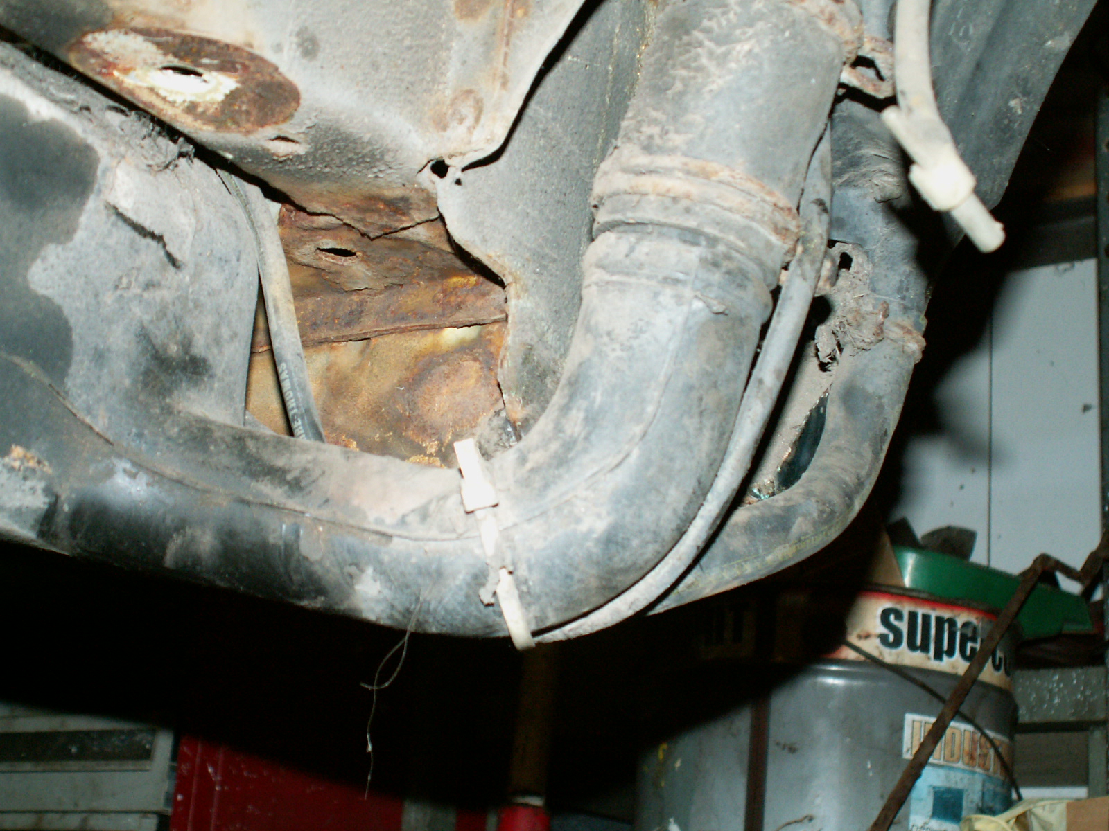
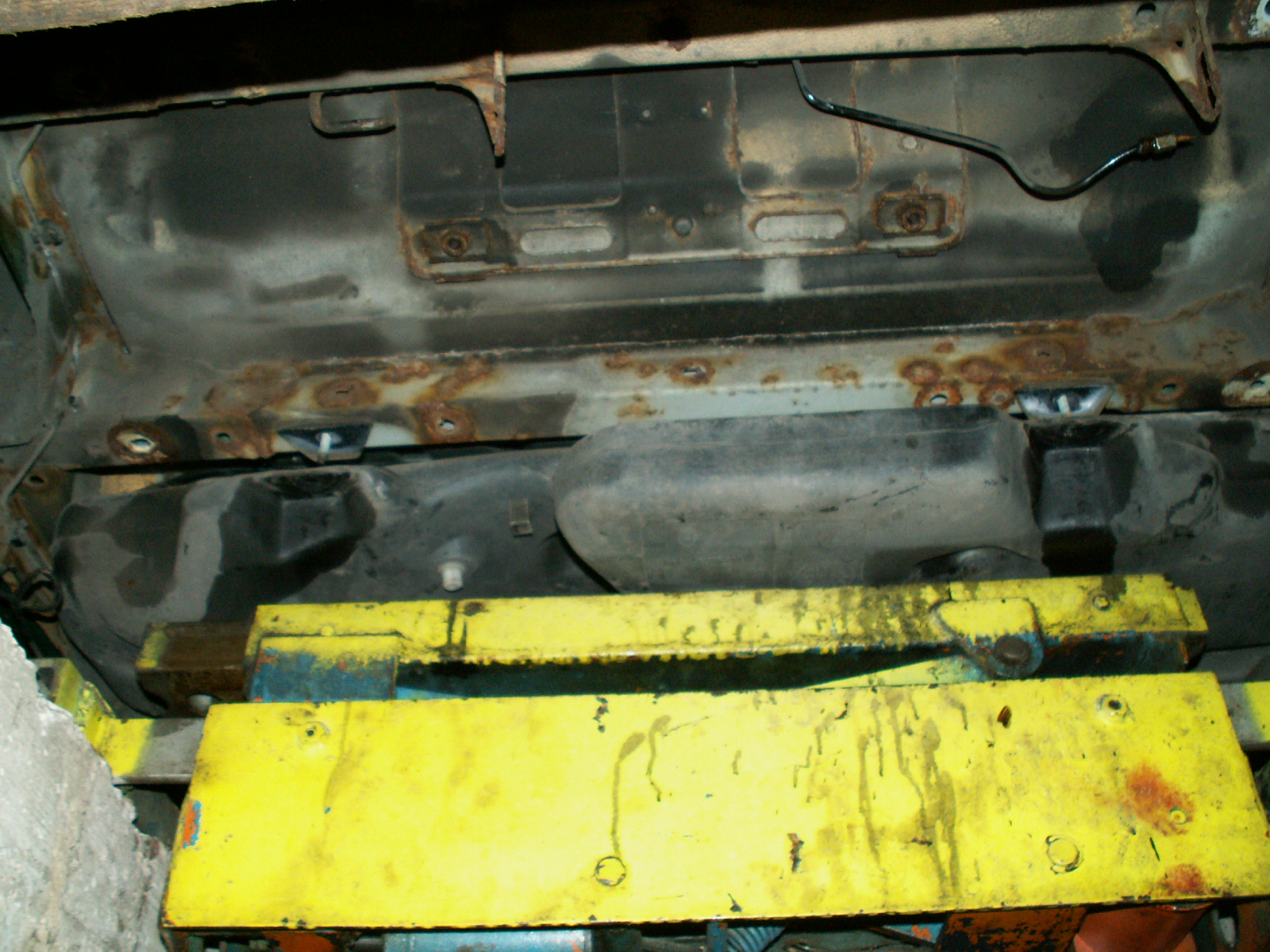
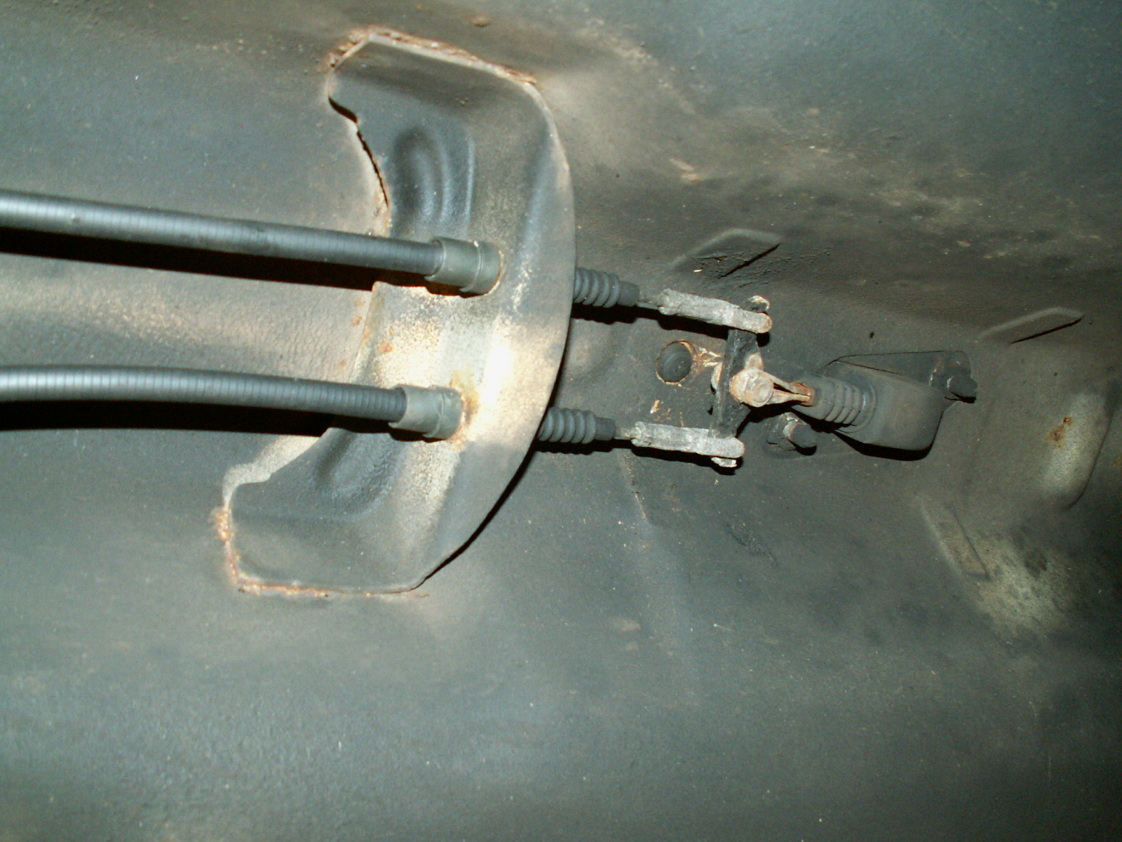
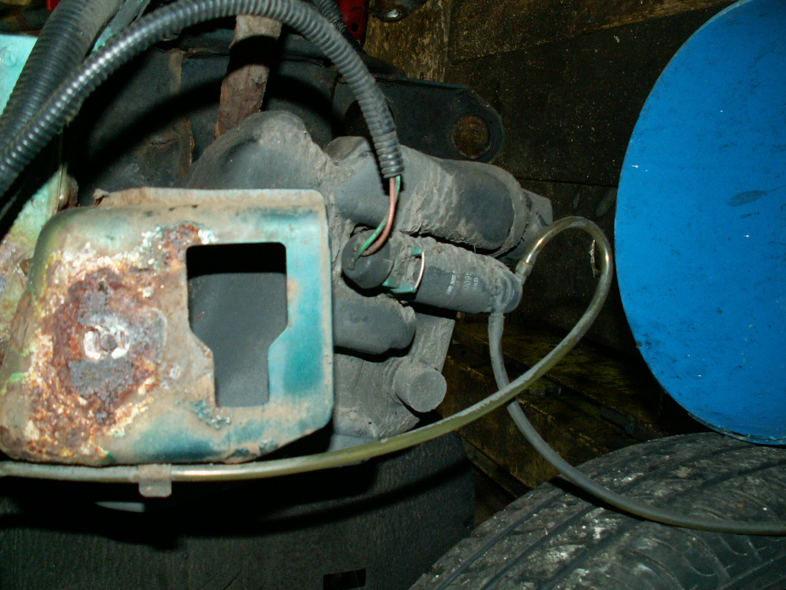
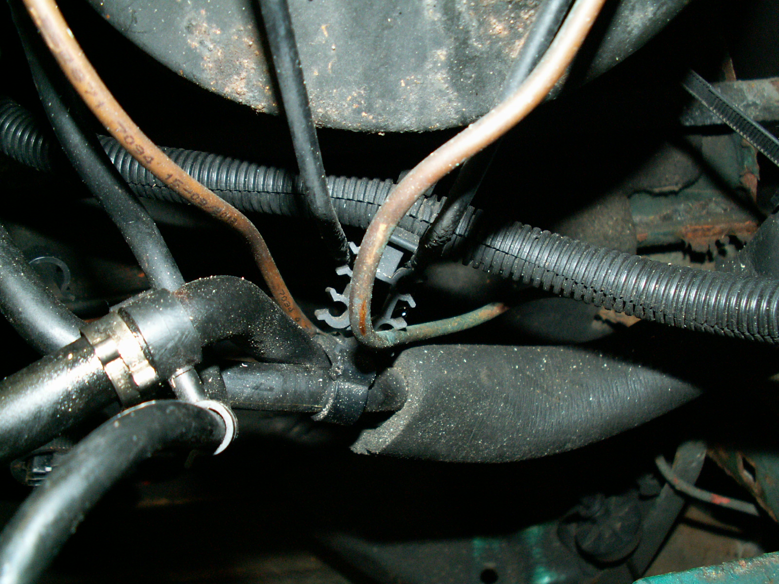
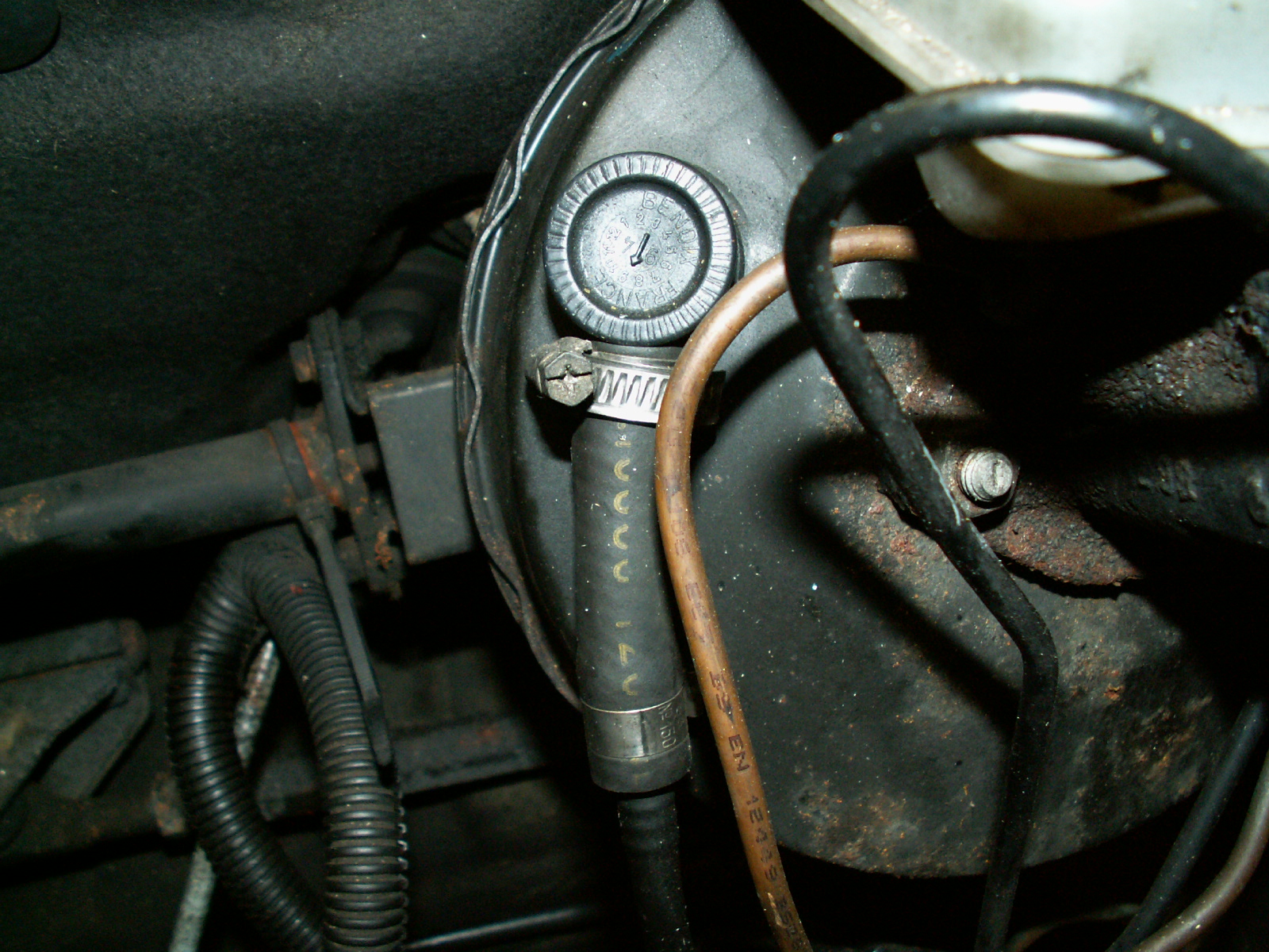
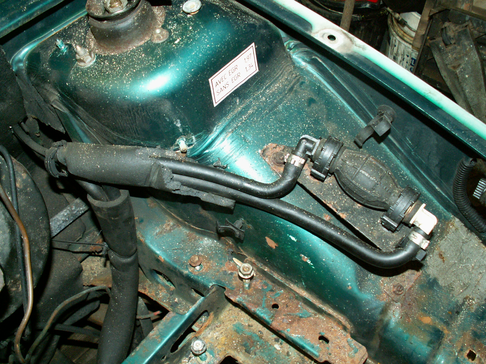
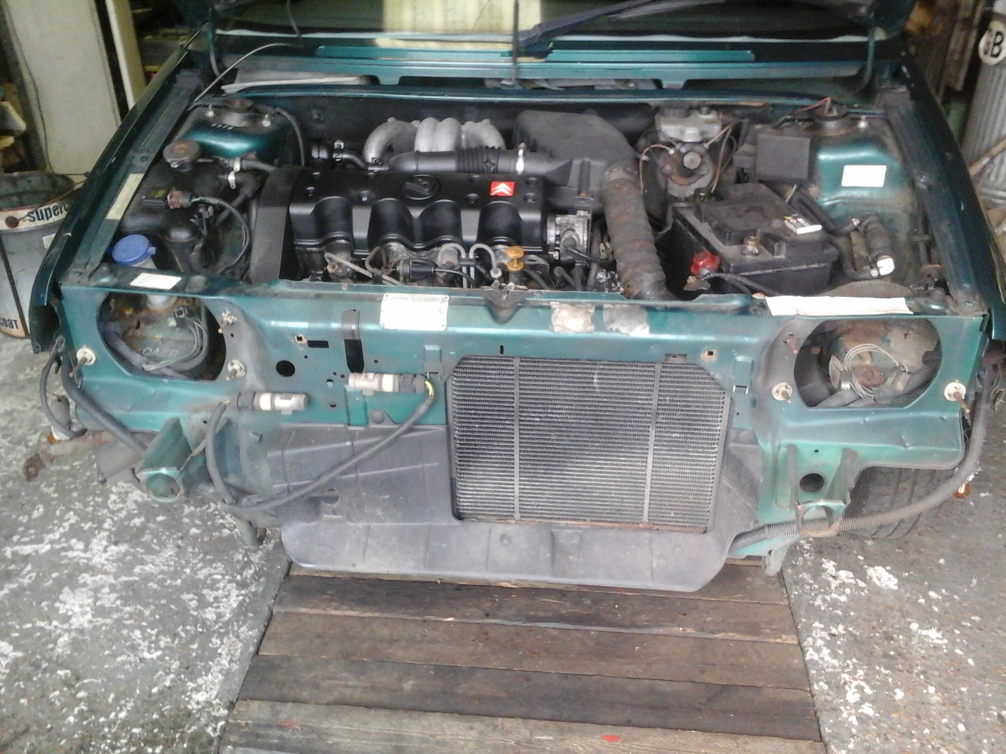
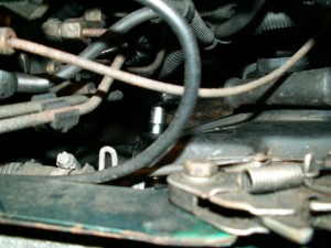
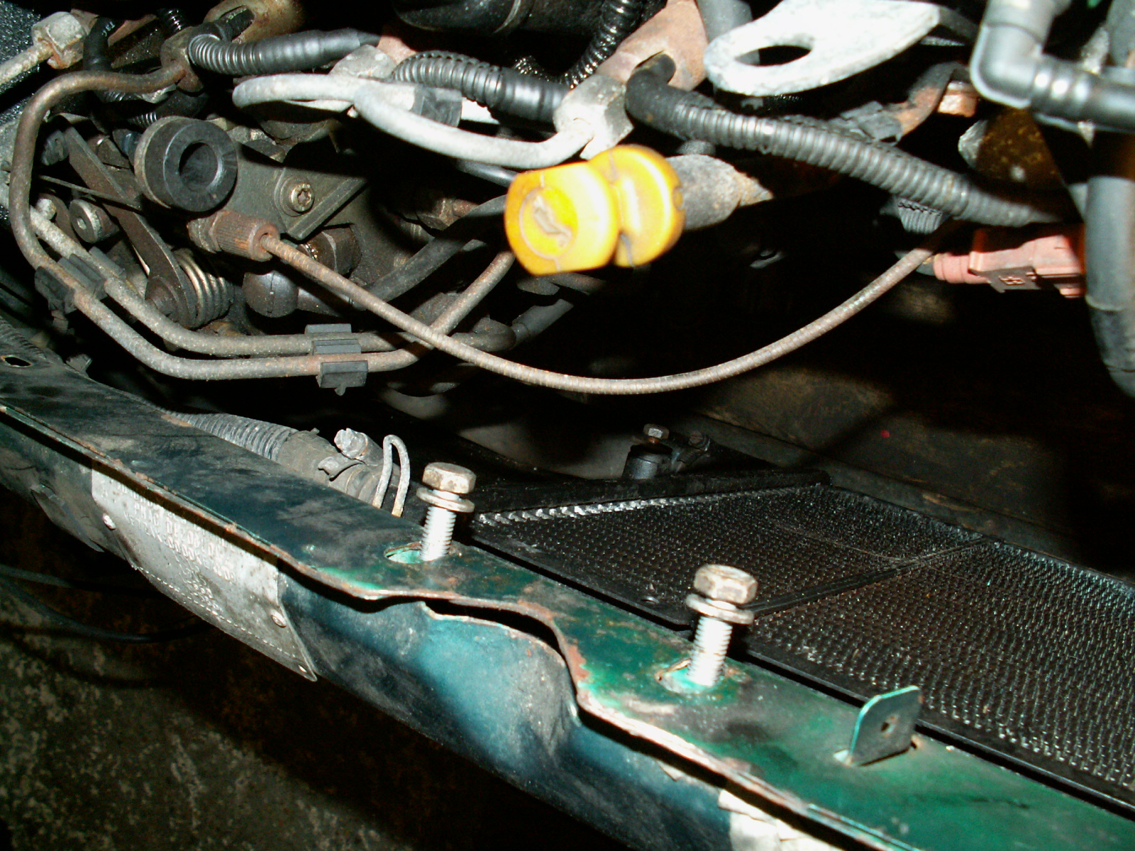
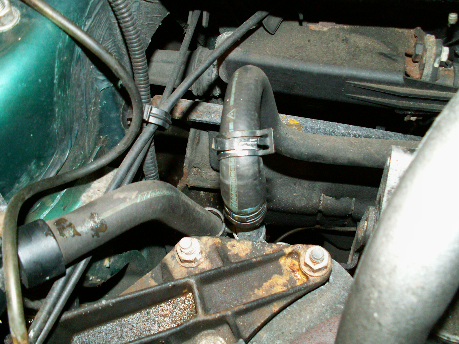
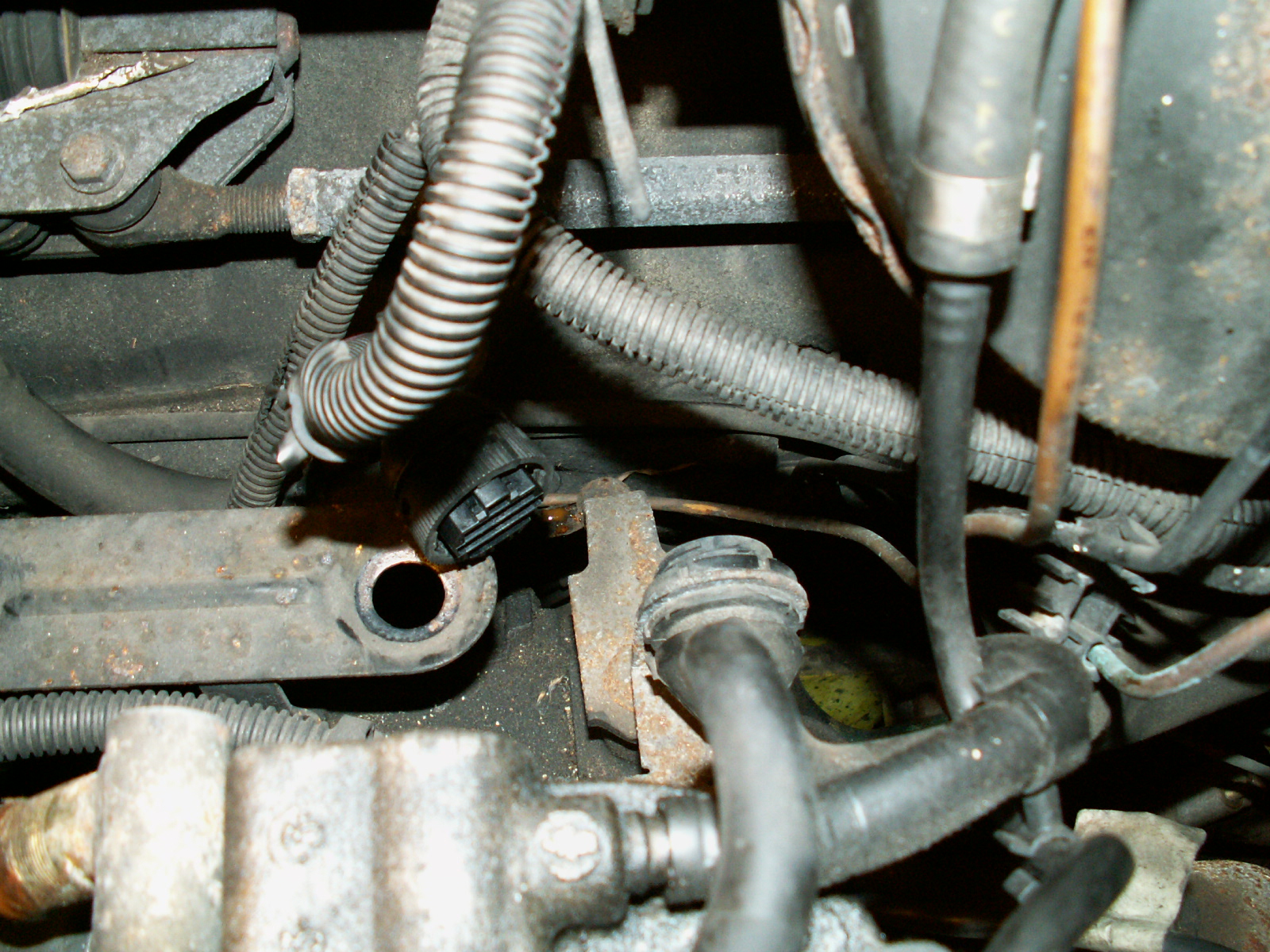
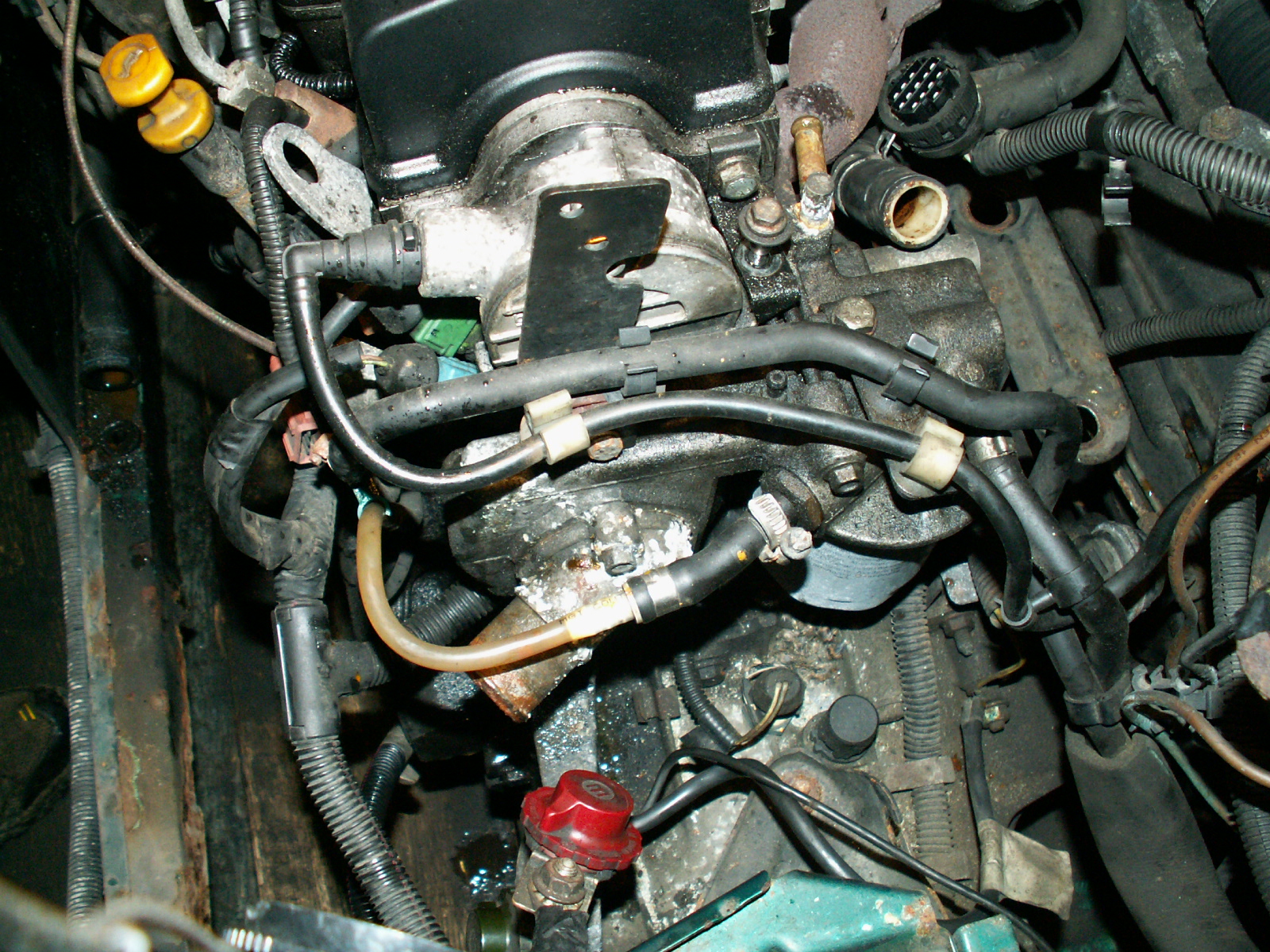
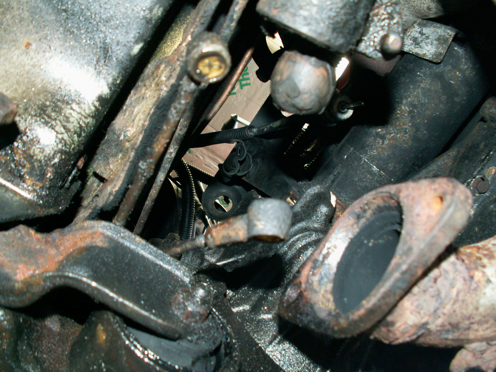
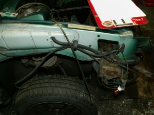
11. Now onto the fuel pipes, note how it is all routed under the servo, note also the copper replacement brake pipes! Not the neatest job I’ve seen.

KONICA MINOLTA DIGITAL CAMERA

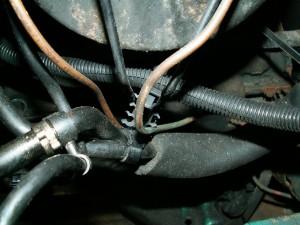
12. Disconnect the vacuum pipe from the servo.

KONICA MINOLTA DIGITAL CAMERA

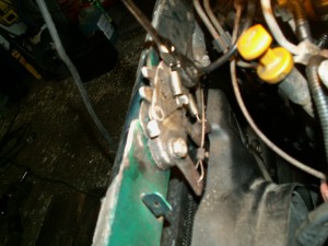
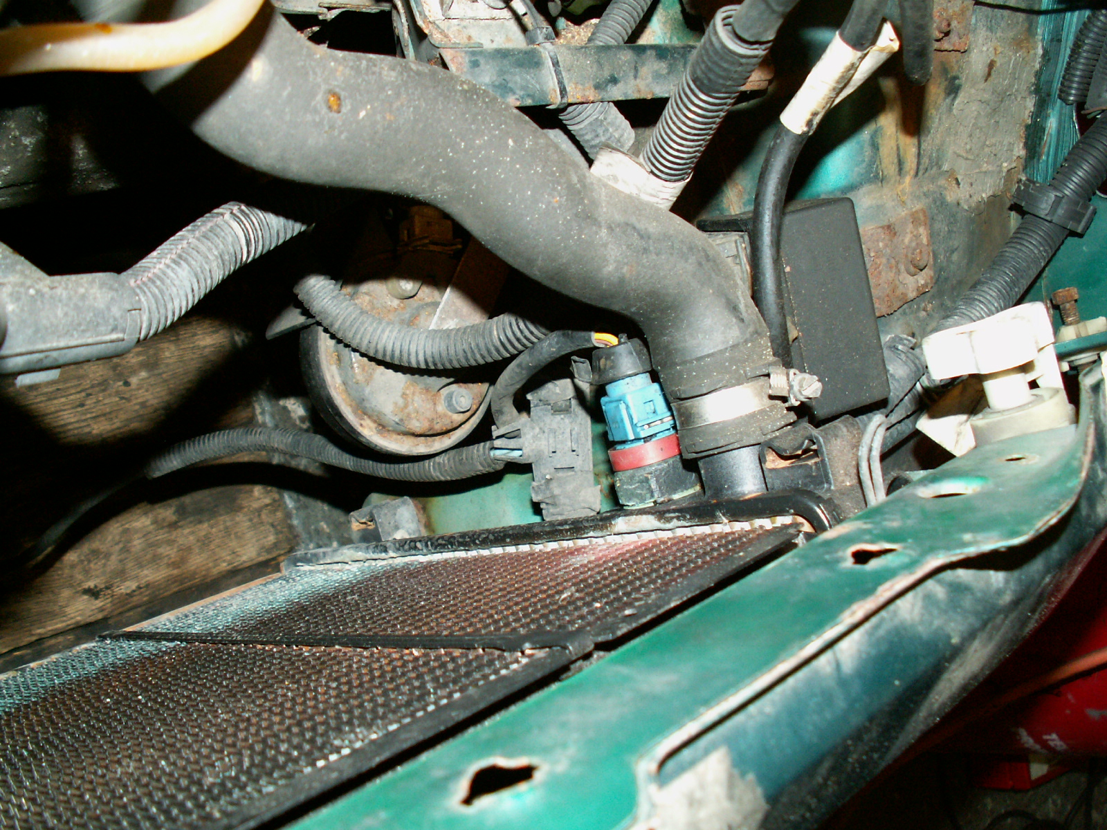
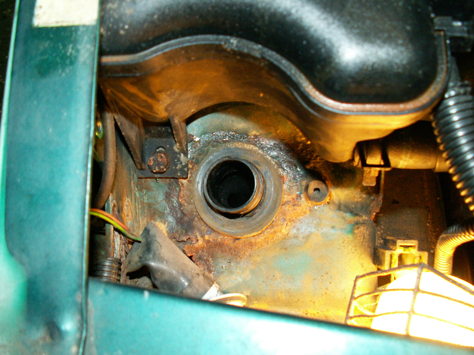
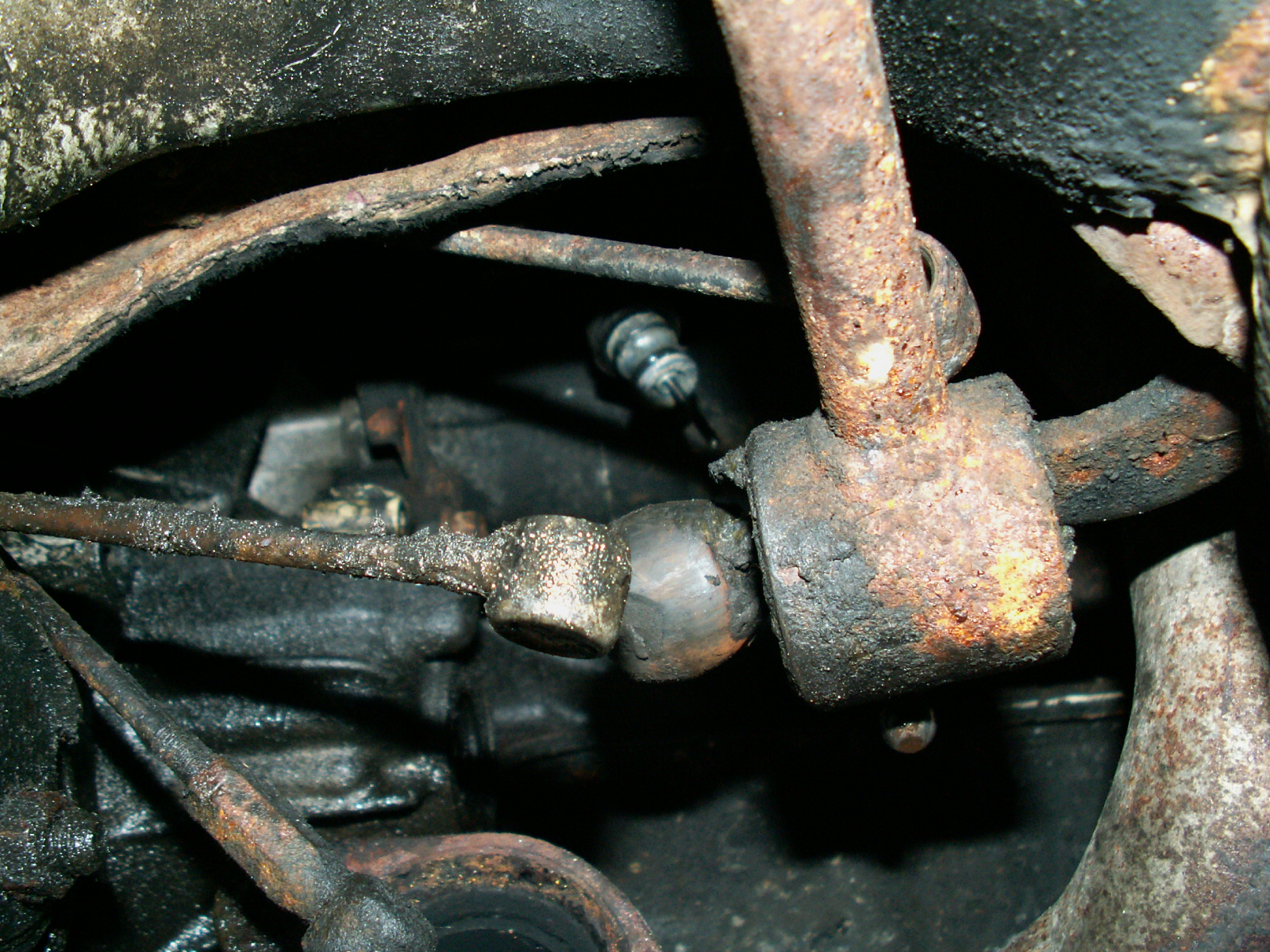
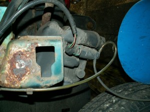
13. Unbolt the priming pump from the inner wing and disconnect the fuel pipes. Flow is at the top, return at the bottom.

KONICA MINOLTA DIGITAL CAMERA

14.  Remove the small plastic guide from the slam panel.

KONICA MINOLTA DIGITAL CAMERA

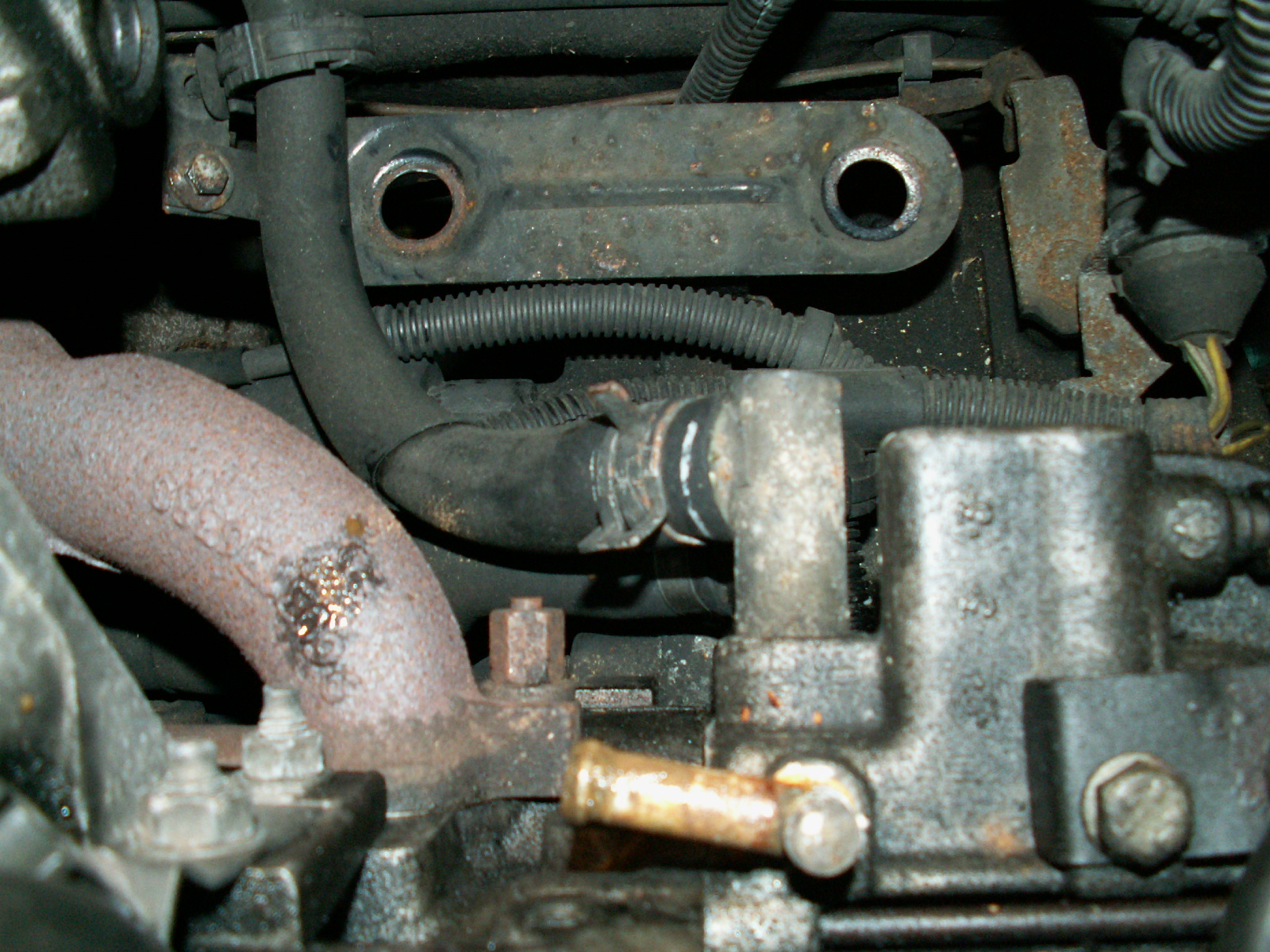
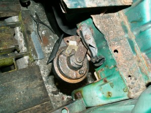
15. Now unbolt the horn from the bracket (13mm) and the bracket from the inner wing (10mm)

KONICA MINOLTA DIGITAL CAMERA

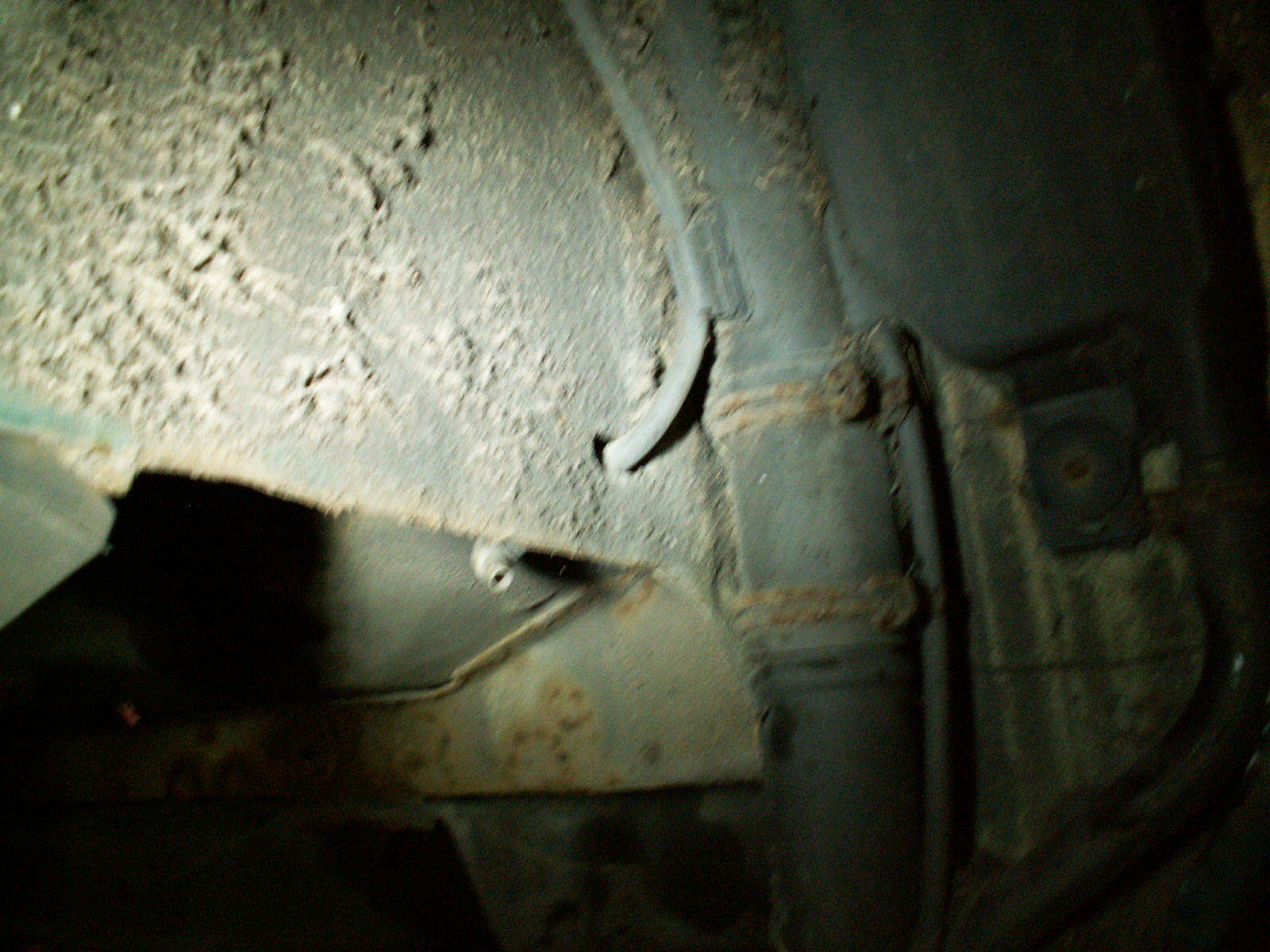
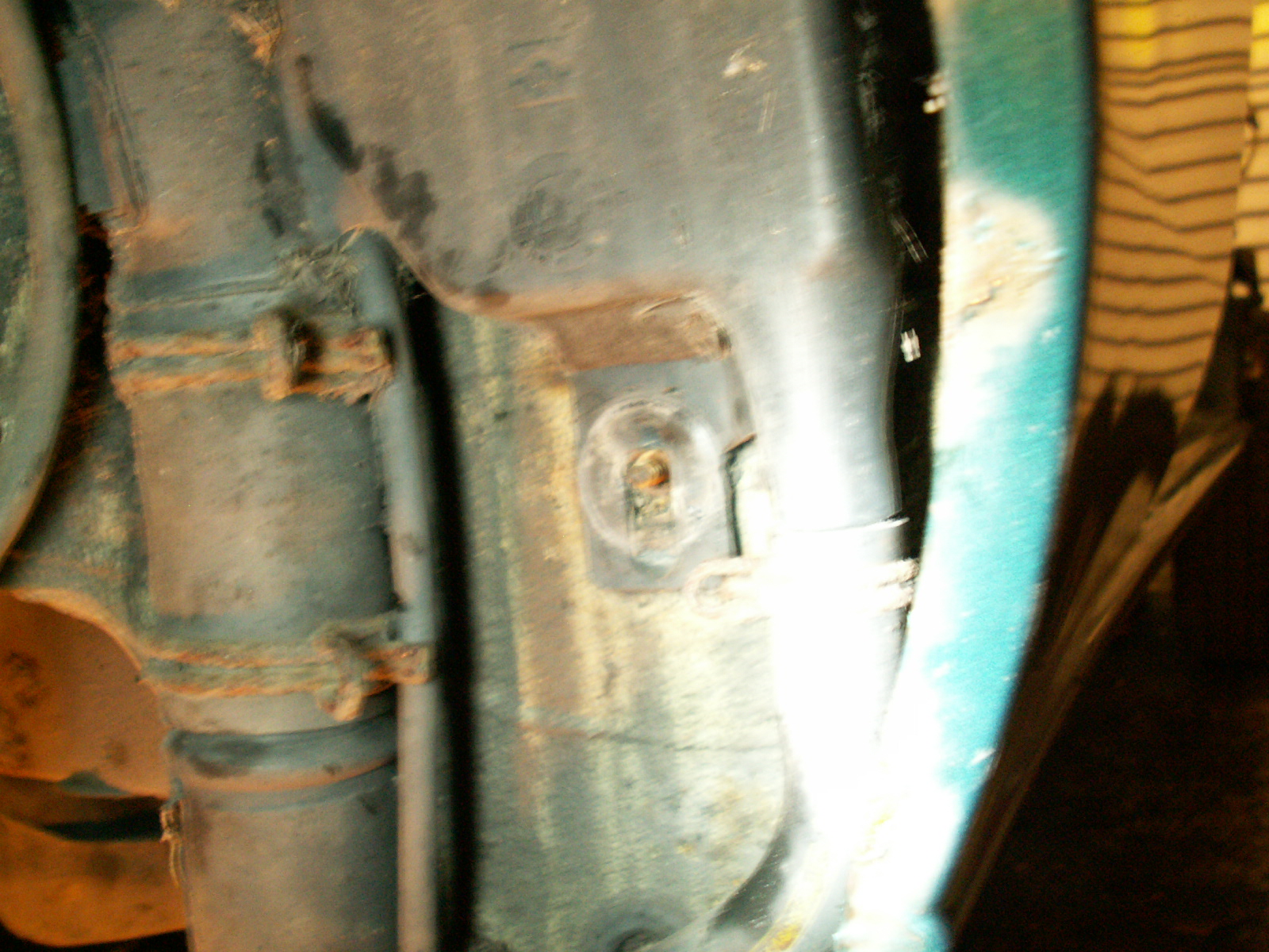
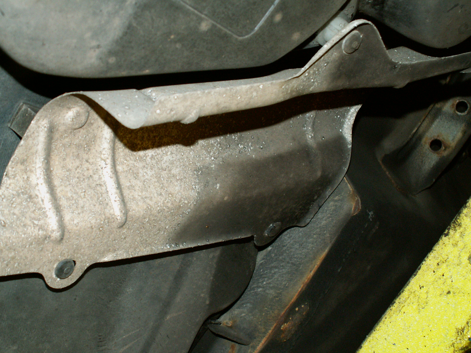
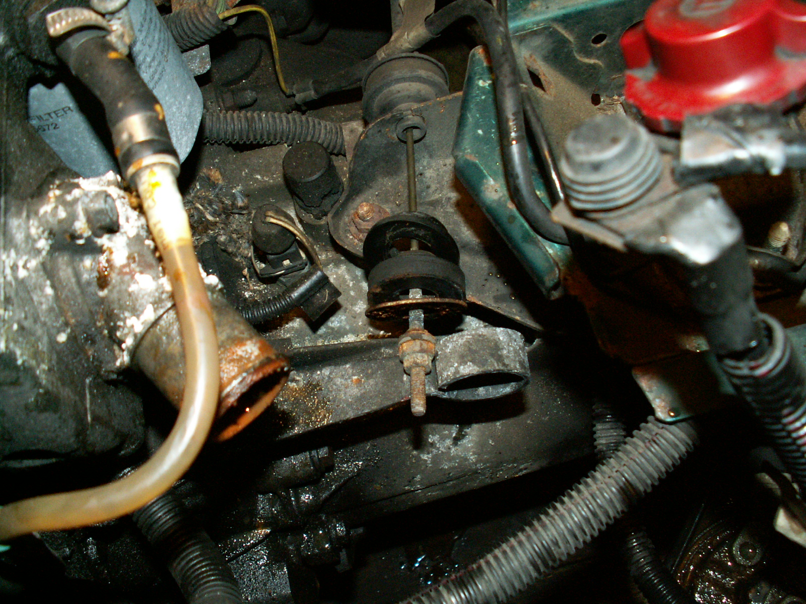
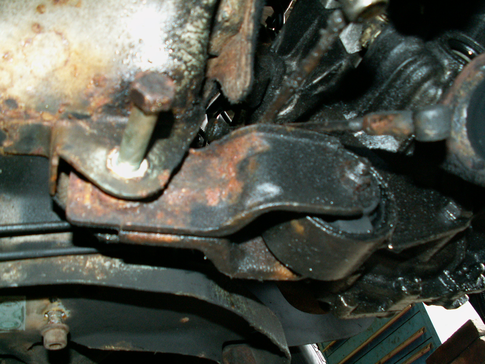
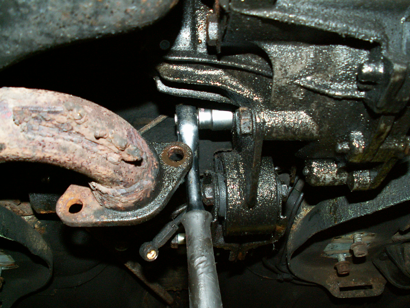
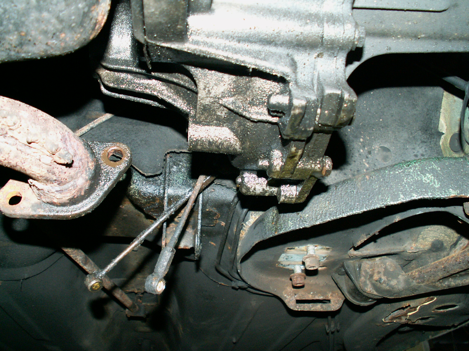
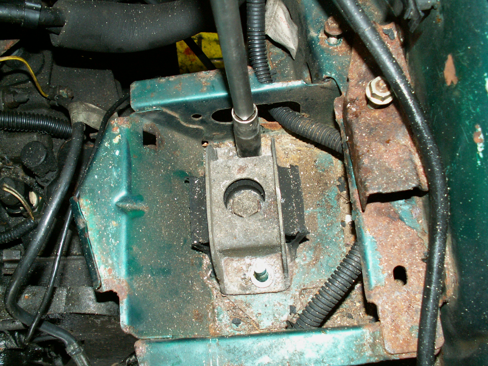
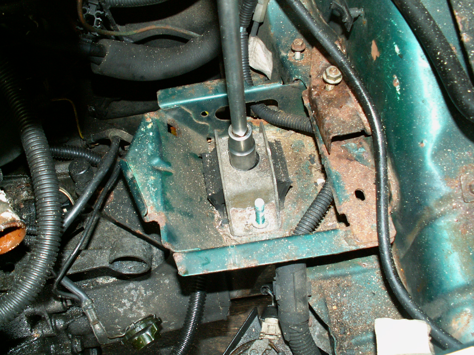
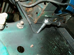
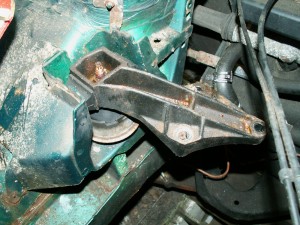
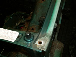
16. Now remove the drivers side engine mount. The top nut was seized and was just turning and stressing the rubber so I undid the larger nut accessible underneath from the inner wing, (hidden behind a plastic cover)

KONICA MINOLTA DIGITAL CAMERA

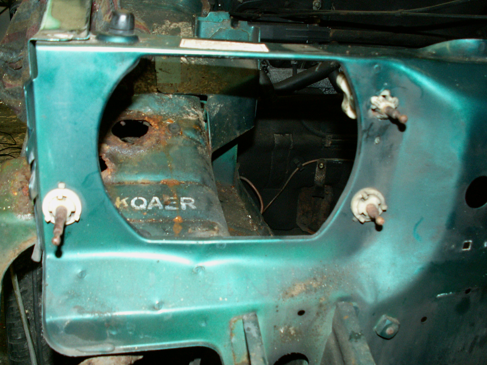
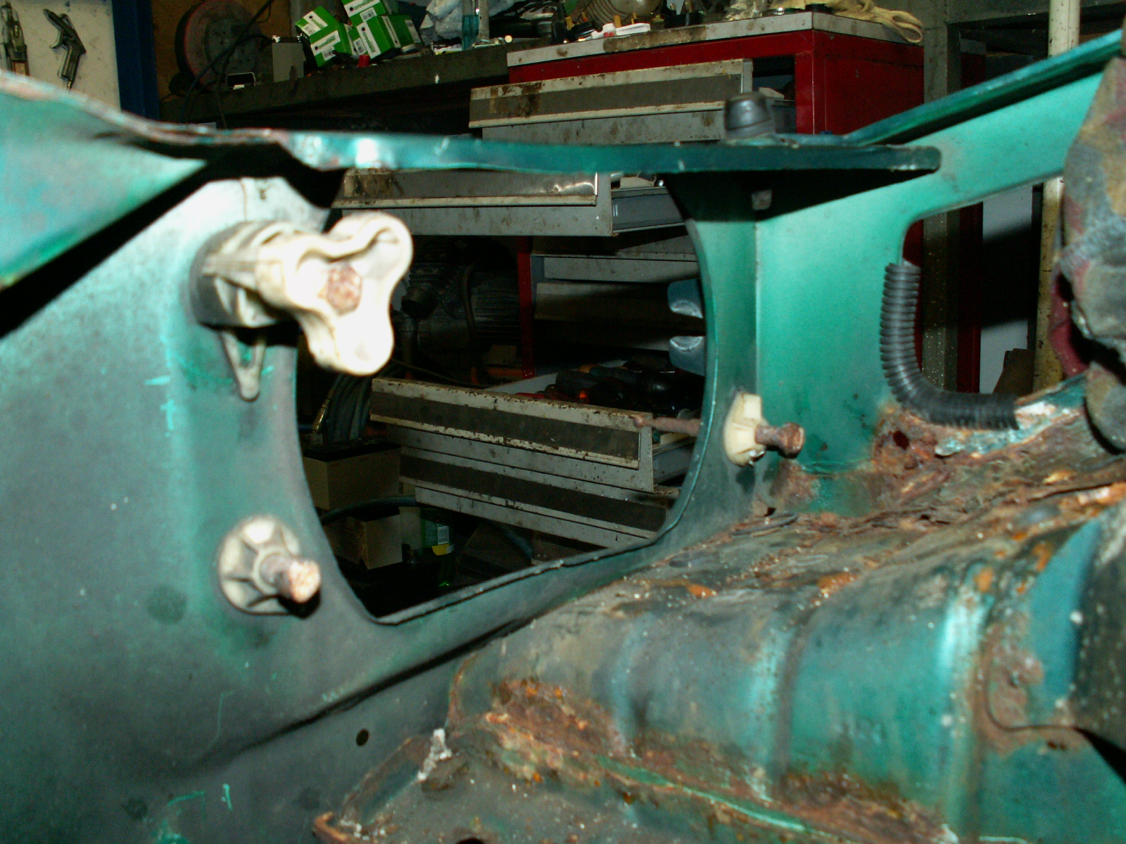
17. Remove the three headlamp adjusters from the passenger side, noting their orientation. The two lower ones are held in with a plastic locking ring on the outside. The upper one just twists out.

KONICA MINOLTA DIGITAL CAMERA

18. Same with the drivers side.

KONICA MINOLTA DIGITAL CAMERA

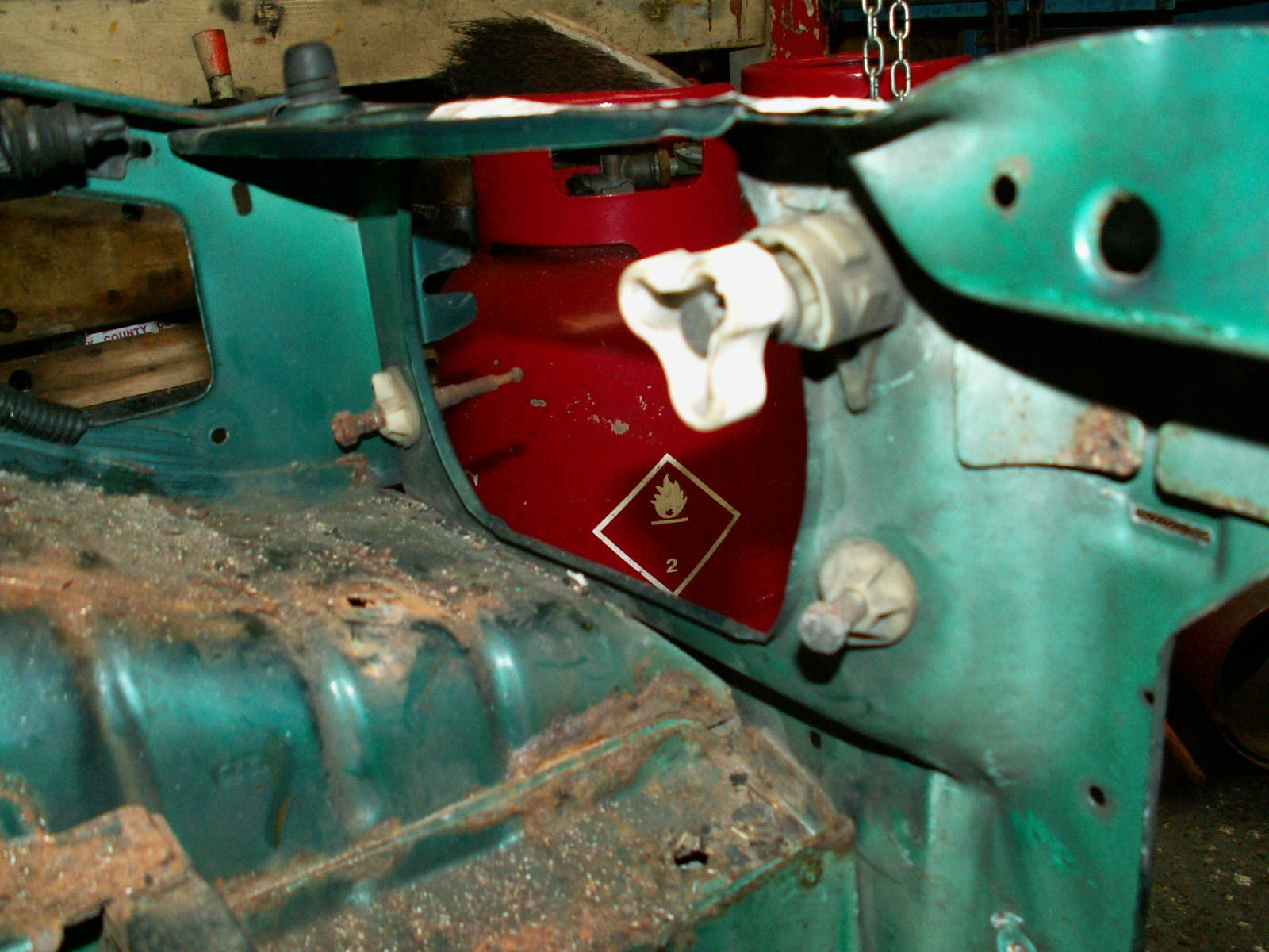
19. This is the view from behind.

KONICA MINOLTA DIGITAL CAMERA

20. And the other side.

KONICA MINOLTA DIGITAL CAMERA

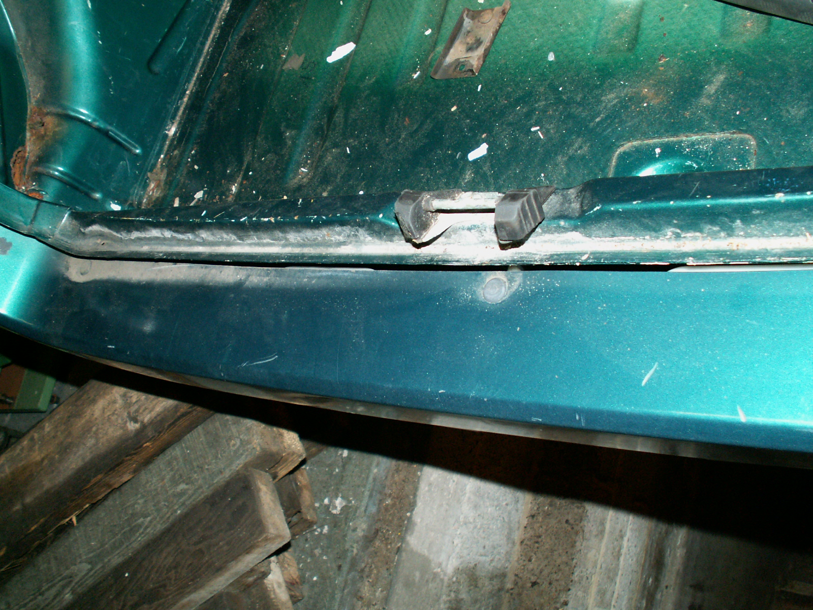
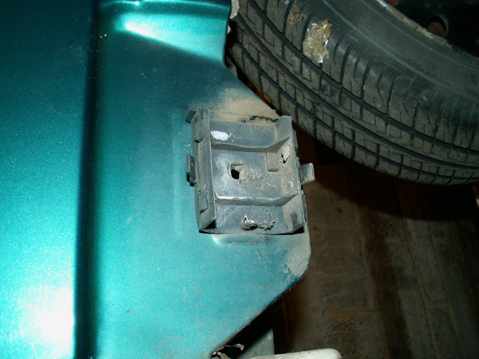
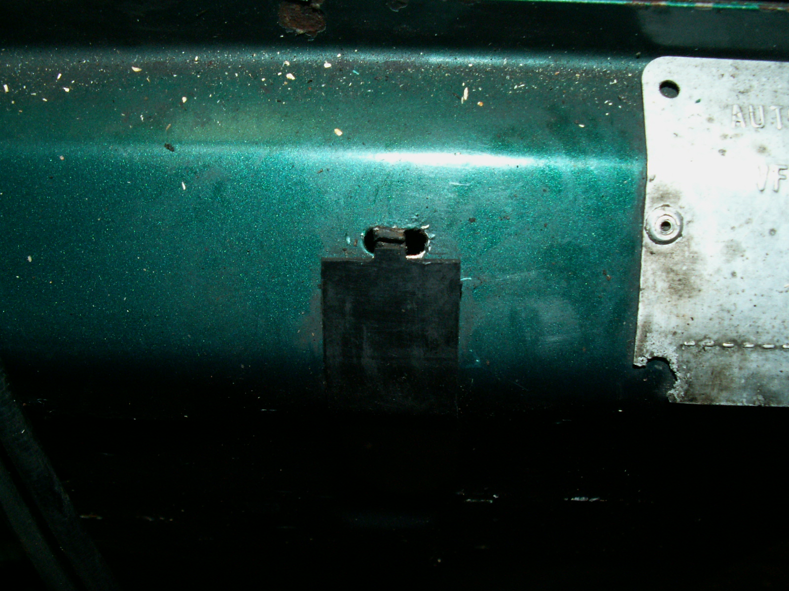
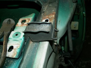
21. Remove the bonnet rest rubbers, two square blocks, one either side, just lift off – held on by a spring clip.

KONICA MINOLTA DIGITAL CAMERA

22. Then the front adjustable rubber stops, these simply unscrew.

KONICA MINOLTA DIGITAL CAMERA

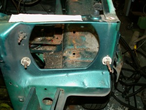
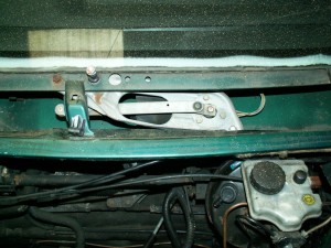
23. Finally at the front is the windscreen wiper moter and mechanism. The AX has a single wiper and the whole unit is held in with a 13mm nut and 13mm nut & bolt. Undo these, unplug the loom and lift out.

KONICA MINOLTA DIGITAL CAMERA

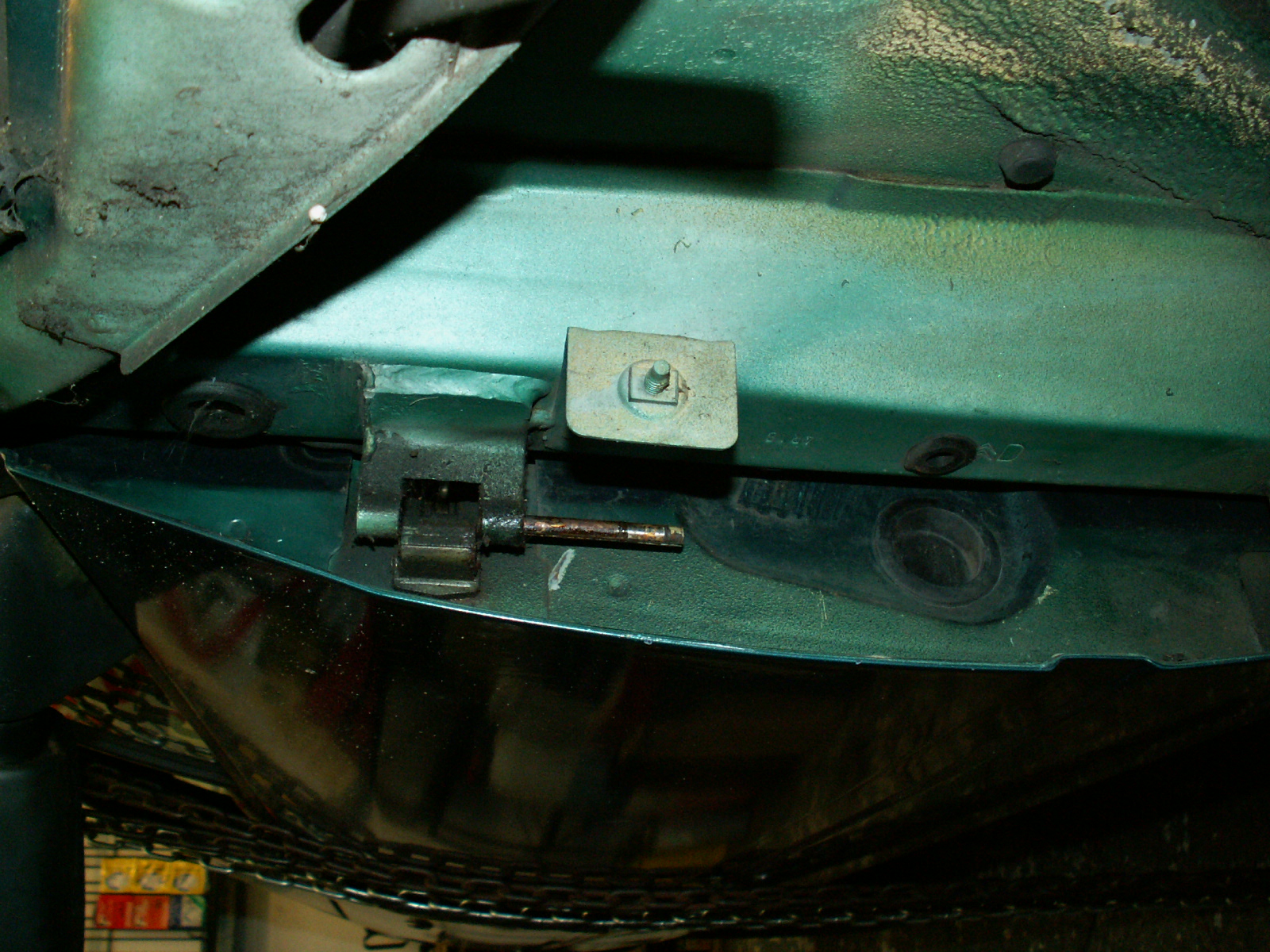
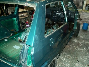
24.  Next it is on to the doors. Bash out the roll pin holding the door stay in place, do theis with the door open. Close the door and then bash the hing roll pins down wards. Use a 40mm long M6 bolt as a drift to drive the pin down through the hinge. Make sure the door is fully shut! When the pins have been drifted through simply lift the door away.

KONICA MINOLTA DIGITAL CAMERA

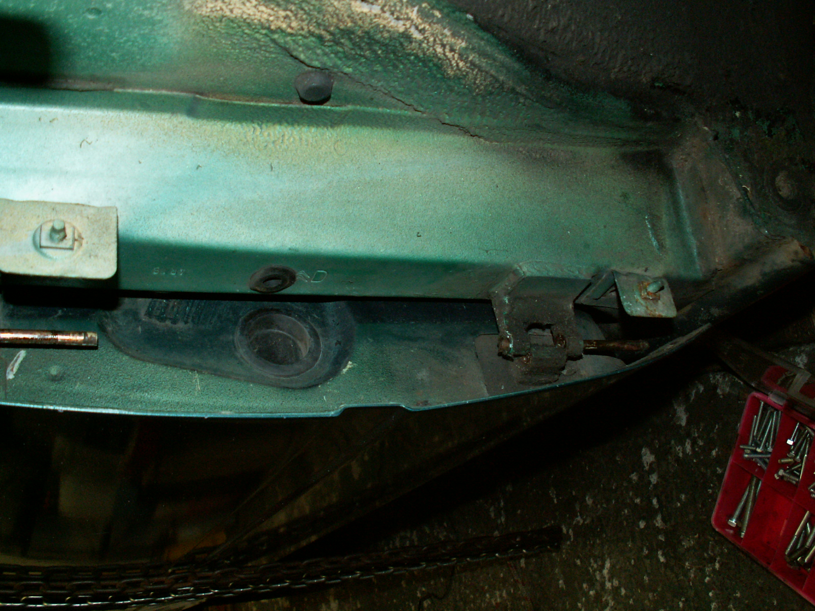
25. Same the other side.

KONICA MINOLTA DIGITAL CAMERA

26. Weight of the door taken by the hoist – though they are not that heavy.

KONICA MINOLTA DIGITAL CAMERA

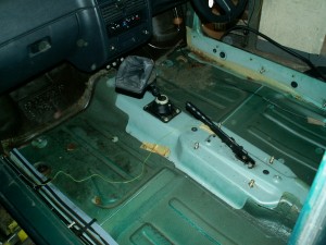
27. Now the interior. I have already removed the seats, the rear seats just lift out, the fronts are held in by four torx bolts. Once out remove the handbrake lever surround, 2 torx screws at the front and one Philips at the back under the ashtray.

KONICA MINOLTA DIGITAL CAMERA

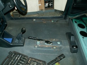
28. Pull out the storagage bin and undo the two 10mm nuts holding the centre console.

KONICA MINOLTA DIGITAL CAMERA

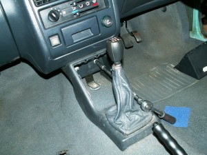
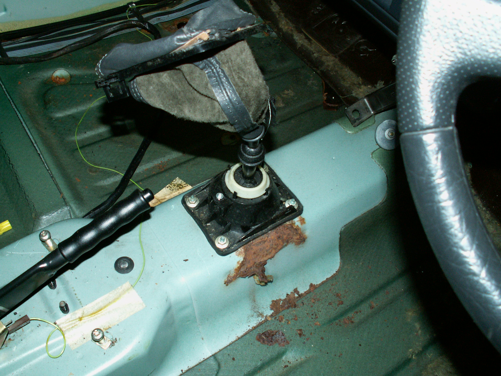
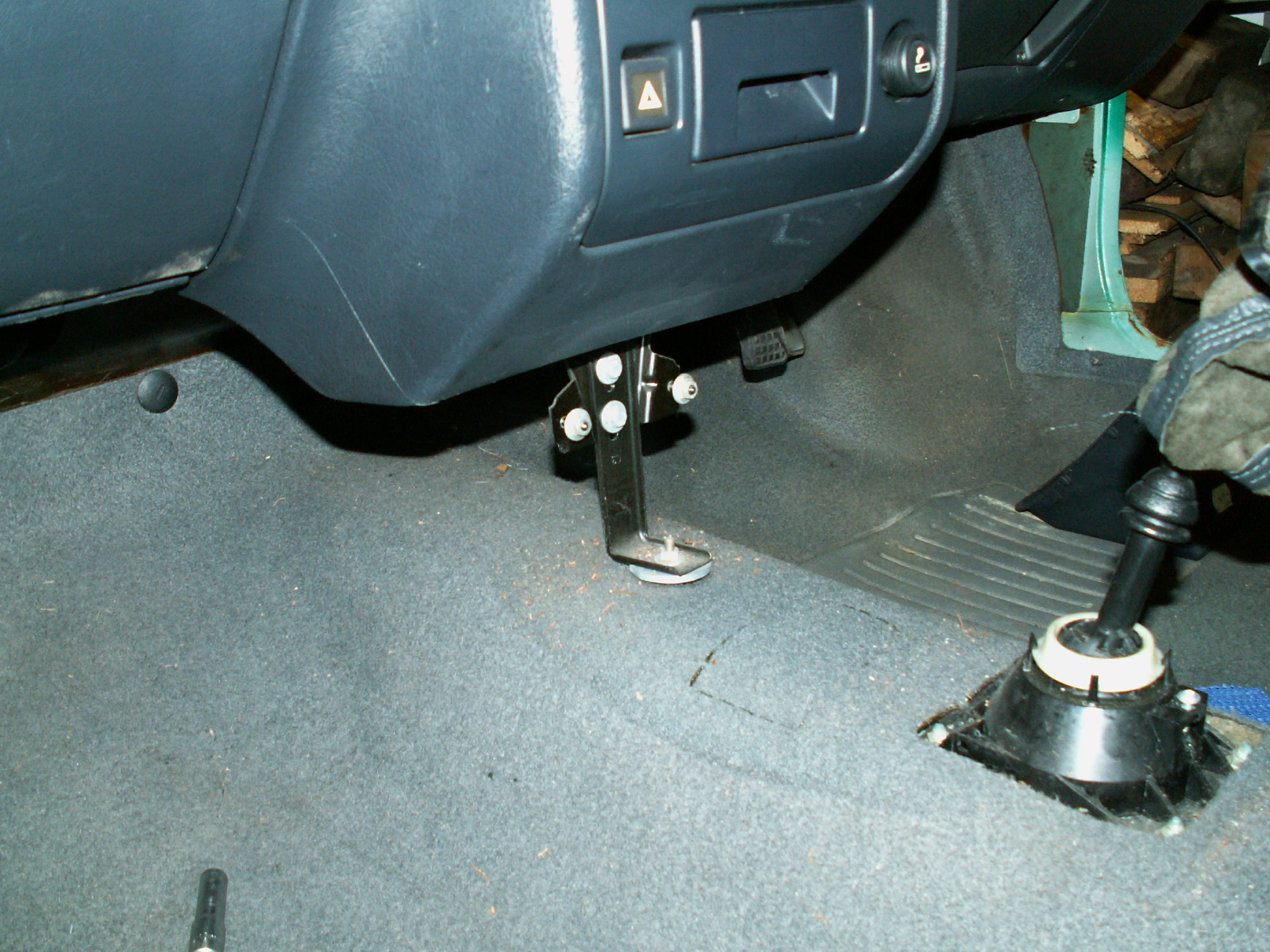
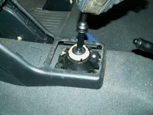
29. Lever up the base of the gear lever gaiter, it just un clips. Then remove the single torx screw holding the rear end of the console.

KONICA MINOLTA DIGITAL CAMERA

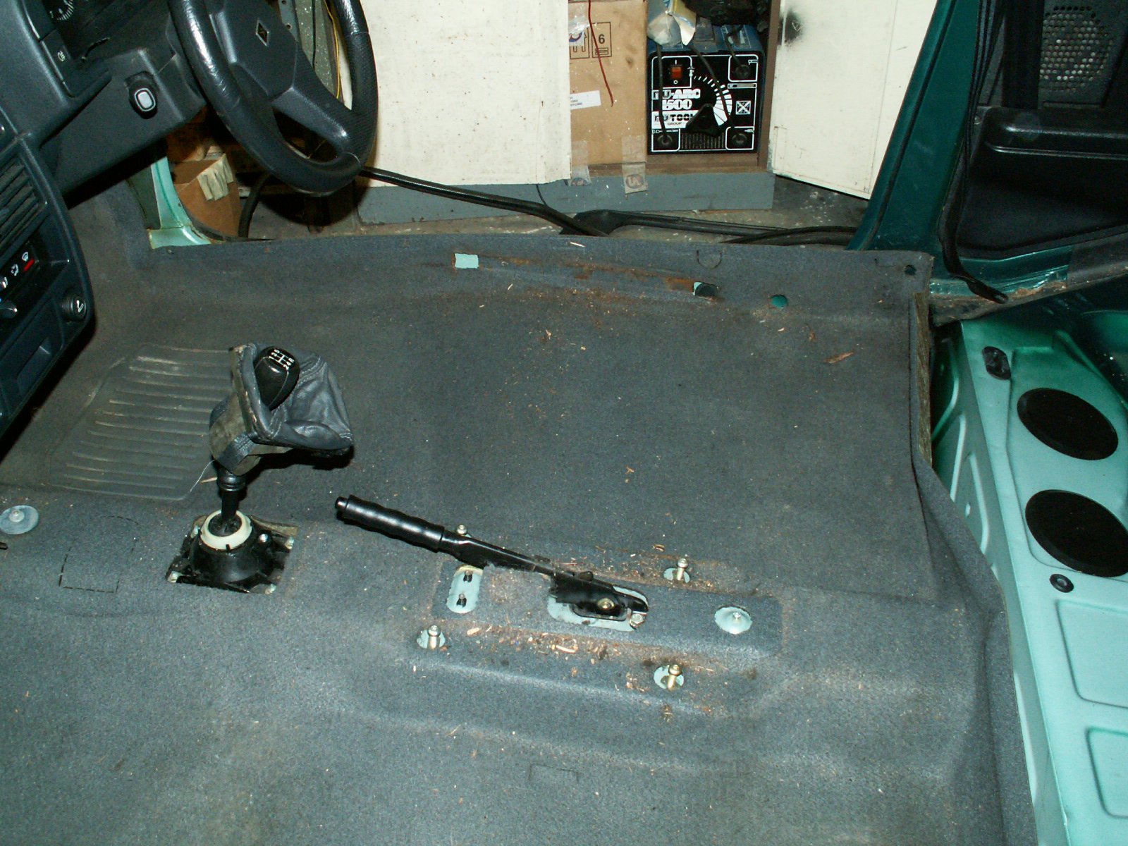
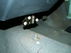
30. Undo the centre bracket, one 10mm nut and two 10mm bolts.

KONICA MINOLTA DIGITAL CAMERA

31. Bracket removed.

KONICA MINOLTA DIGITAL CAMERA

32. Unscrew the six retaining plastics along the front edge of the carpet – they are under the dashboard.

KONICA MINOLTA DIGITAL CAMERA

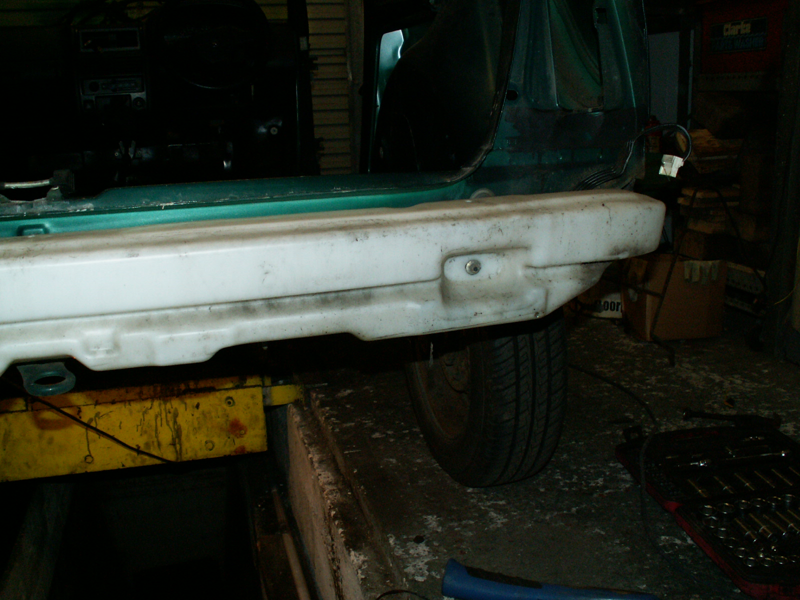
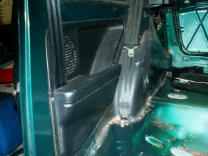
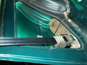
33. Unscrew the Phillips screws holding the door sill trim in place – both sides. Then pull of the door seal rubbers. Also remove the lower seat belt mounts.

KONICA MINOLTA DIGITAL CAMERA

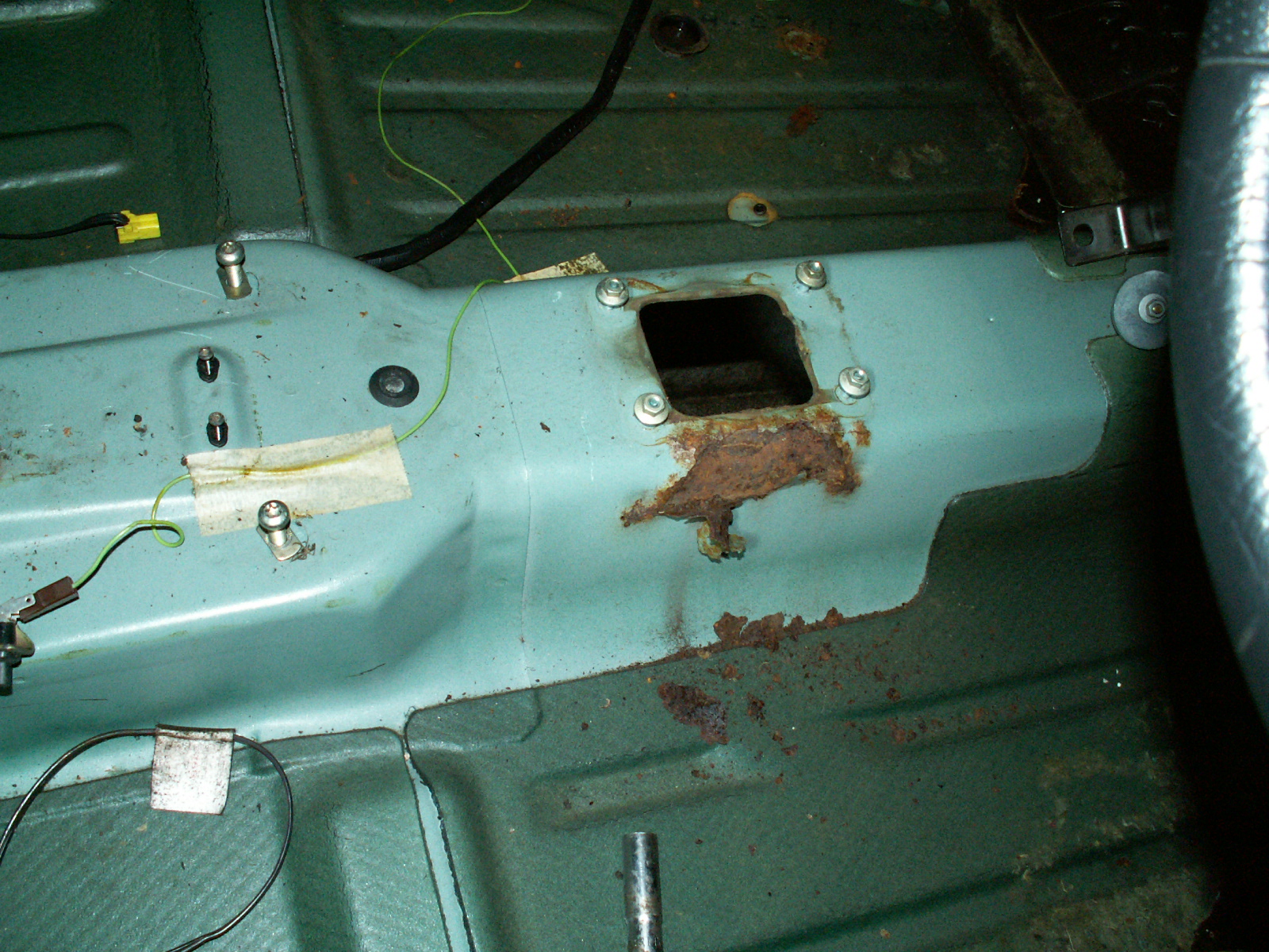
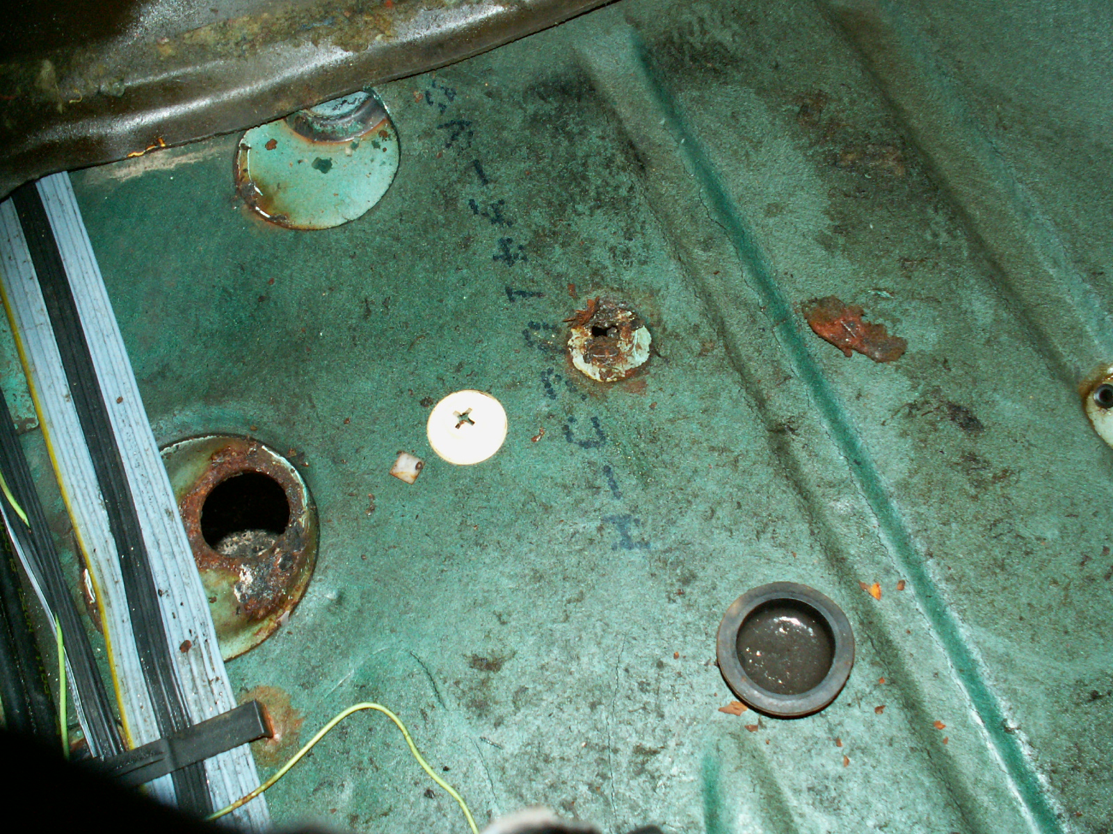
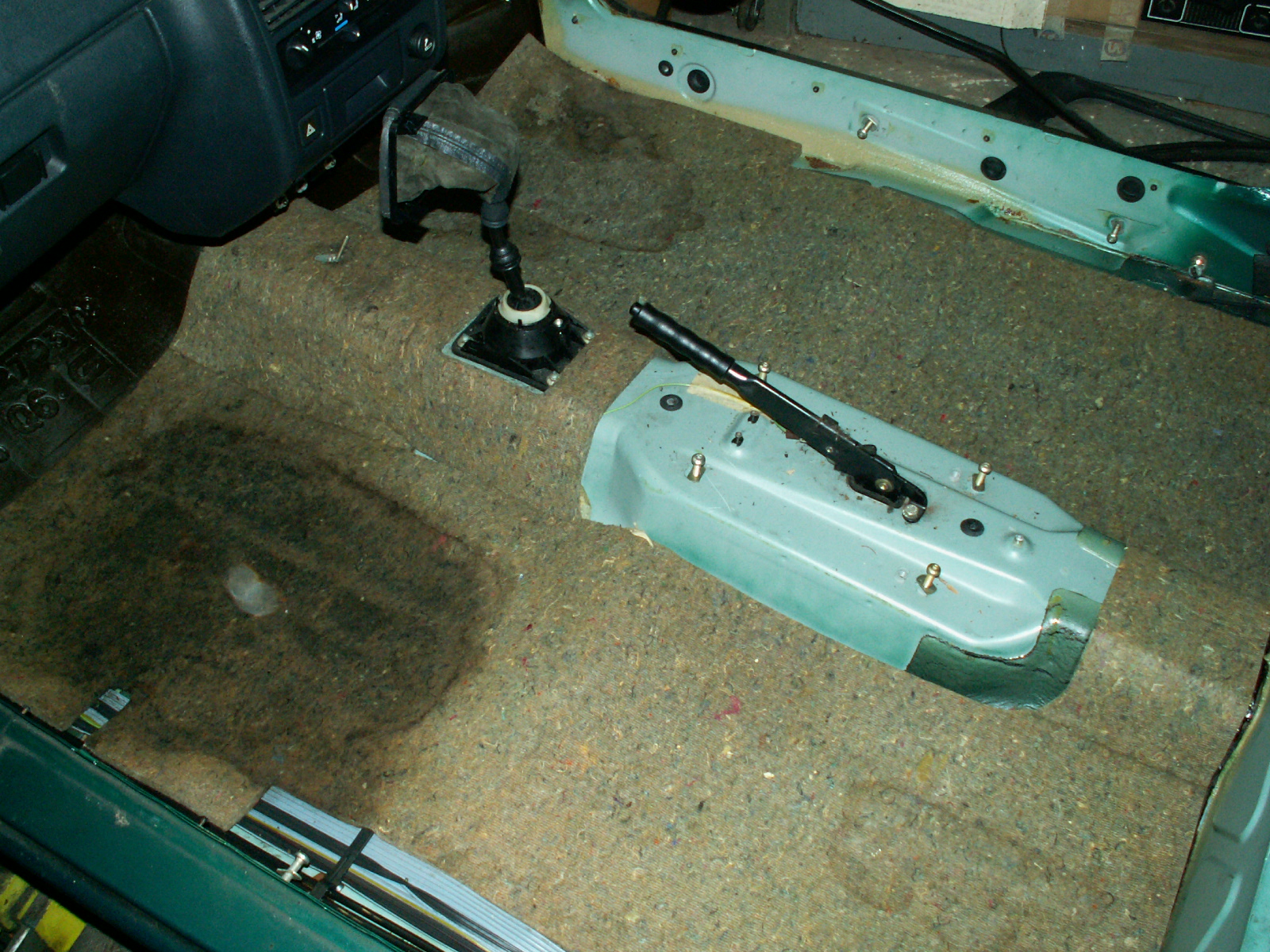
34. Now remove the carpet, feed it carefully over the gear lever and handbrake.

KONICA MINOLTA DIGITAL CAMERA

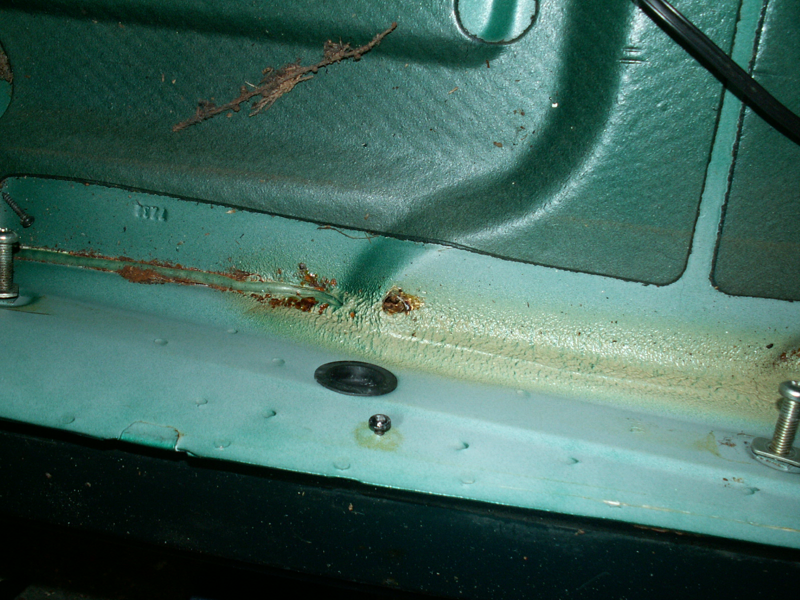
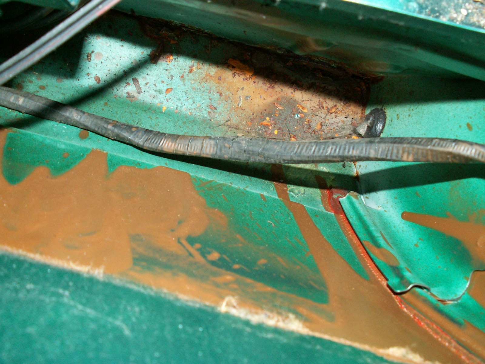
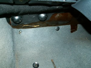
35. Then lift out the sound deadening/underlay – note the wet patch in the passenger foot well!

KONICA MINOLTA DIGITAL CAMERA

36. Undo the two torx screws holding the rear cubbies in place

KONICA MINOLTA DIGITAL CAMERA

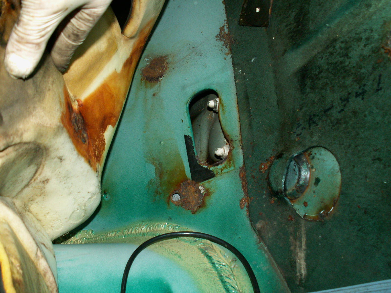
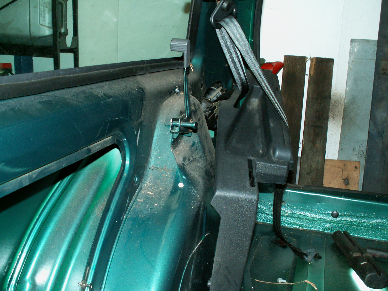
37. Now unbolt the inertia real seat belt and remove the piece of sound deadening.

KONICA MINOLTA DIGITAL CAMERA

38.

KONICA MINOLTA DIGITAL CAMERA

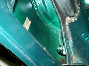
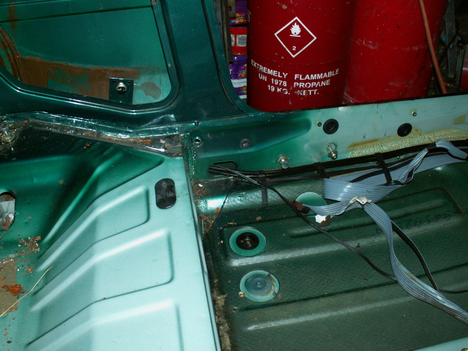
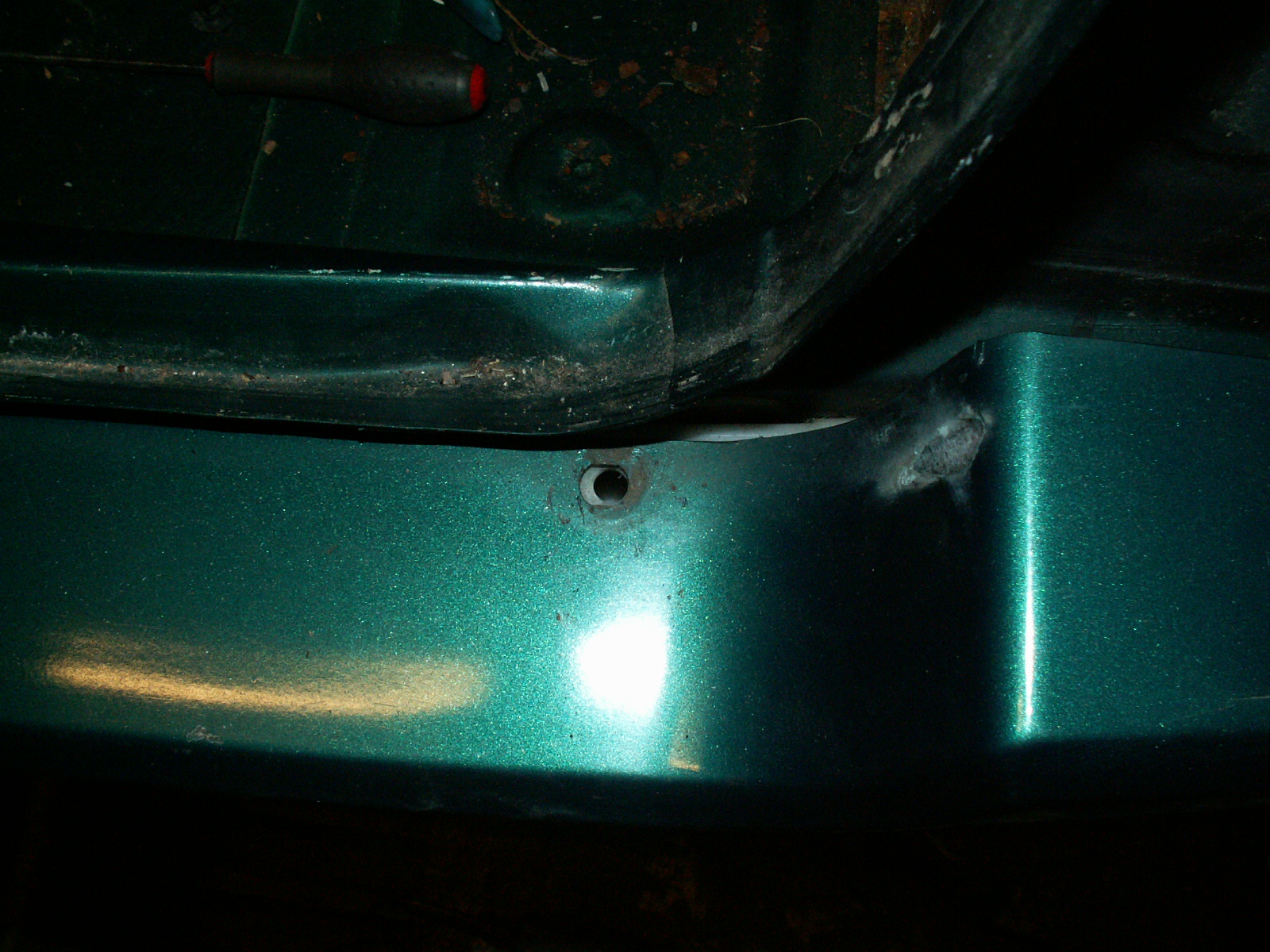
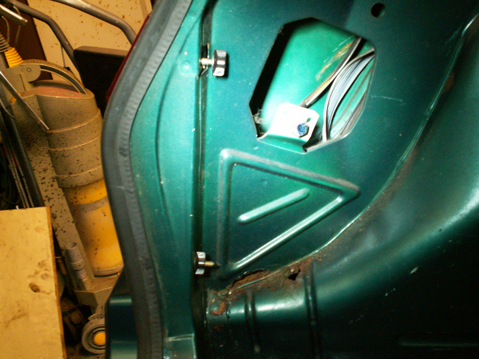
39. Next there are 3 M10 bolts holding the rear trim in place – as well as the top wing nut on the rear lamp. Also undo the rear seat belt mountings.

KONICA MINOLTA DIGITAL CAMERA

40. Shows wing nuts holding rear lamps.

KONICA MINOLTA DIGITAL CAMERA

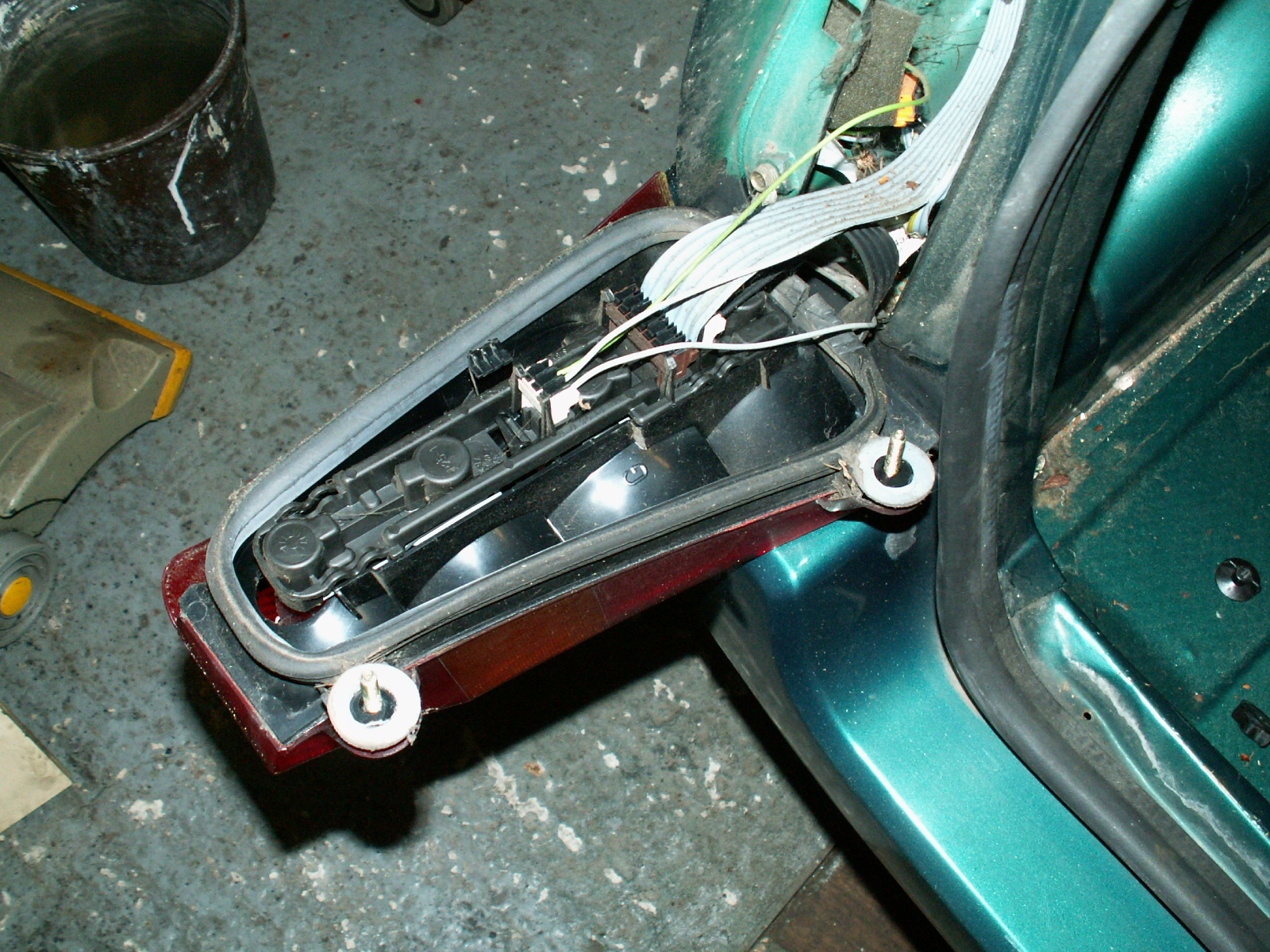
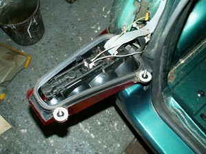
41. Passenger side rear lamp removed, disconnect wiring.

KONICA MINOLTA DIGITAL CAMERA

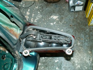
42. And the drivers side.

KONICA MINOLTA DIGITAL CAMERA

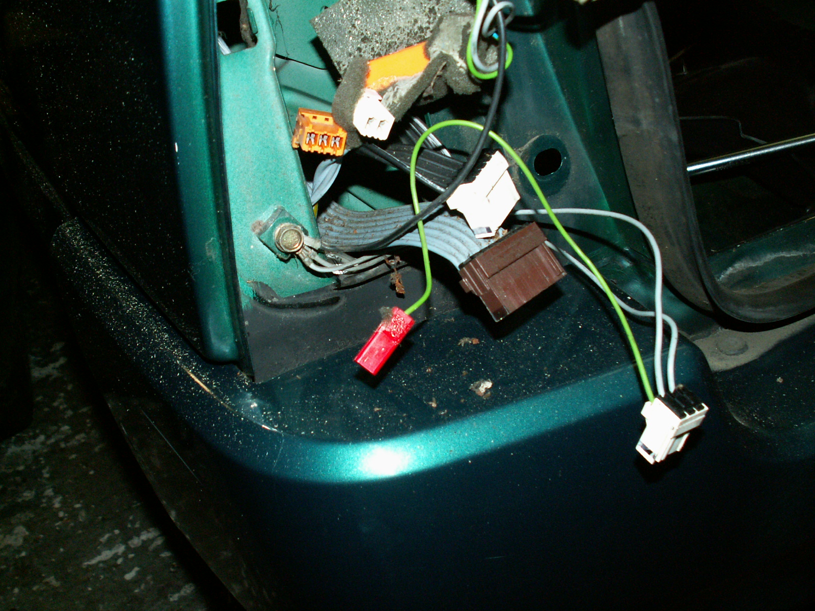
43. Remains of the loom

KONICA MINOLTA DIGITAL CAMERA

44. Drivers side (pics for reference)

KONICA MINOLTA DIGITAL CAMERA

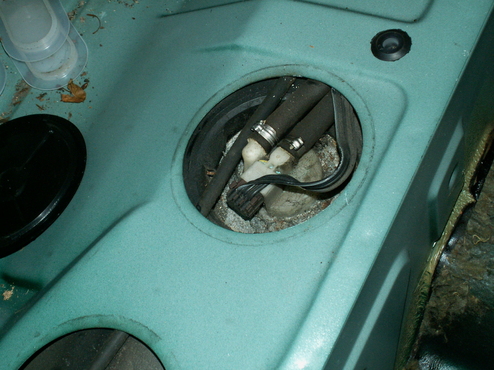
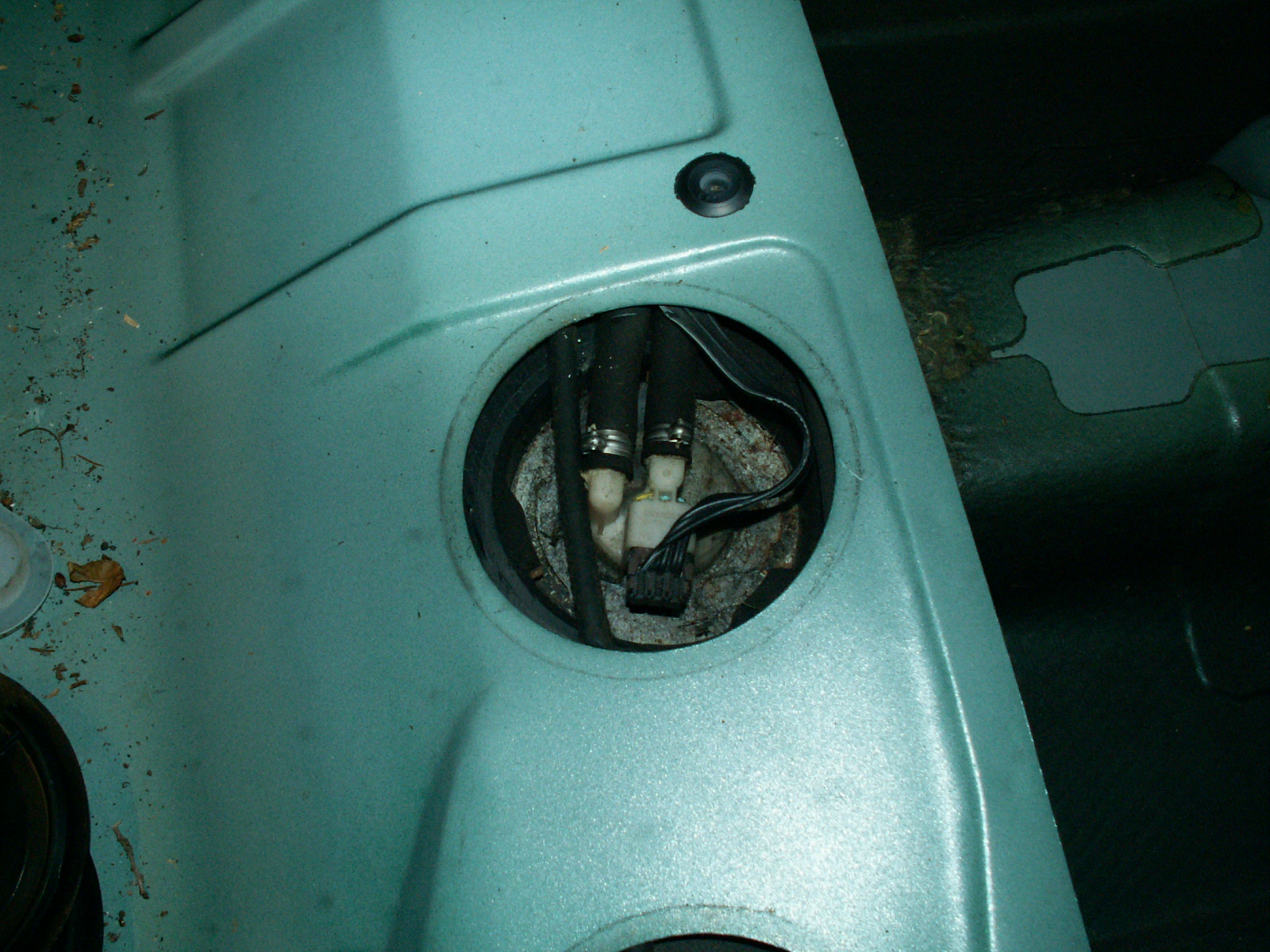
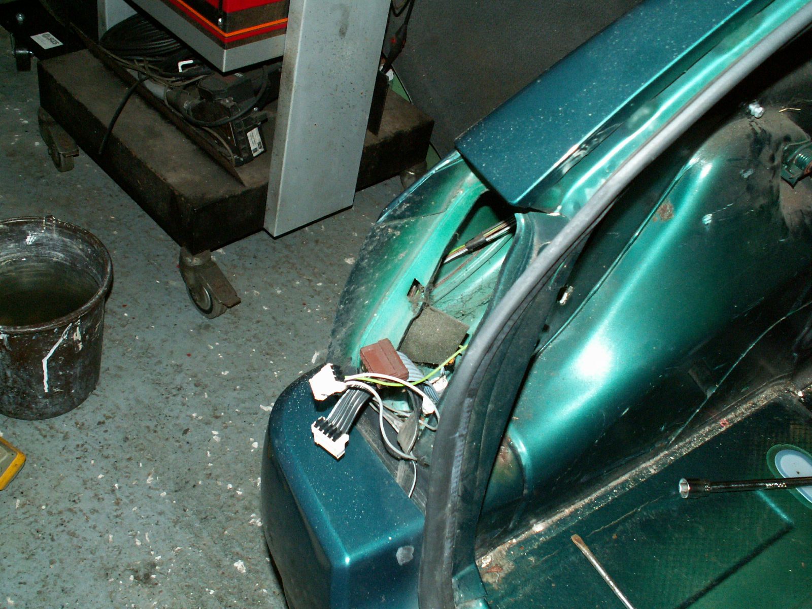
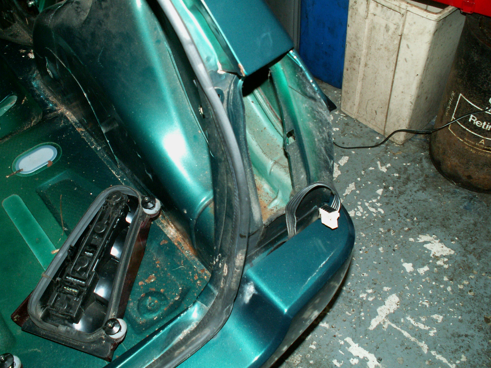
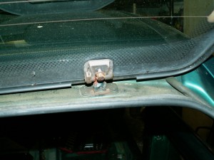
45. Separate off the wires going up to the tailgate.

KONICA MINOLTA DIGITAL CAMERA

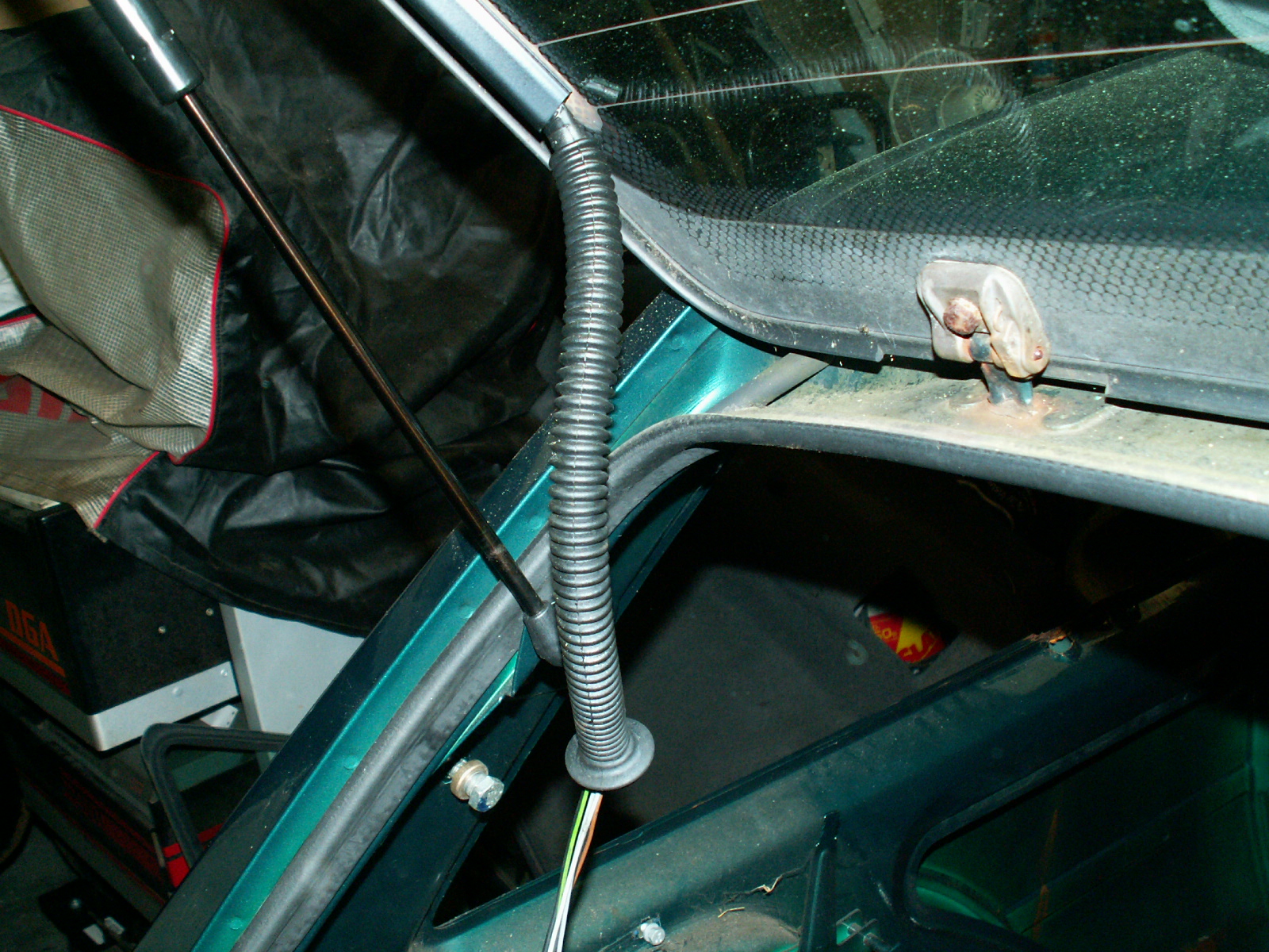
46. Pull out the rubber protection tube that feeds the wires to the tailgate and pull the wires through. The connectors are a bit of a fiddle to get out.

KONICA MINOLTA DIGITAL CAMERA

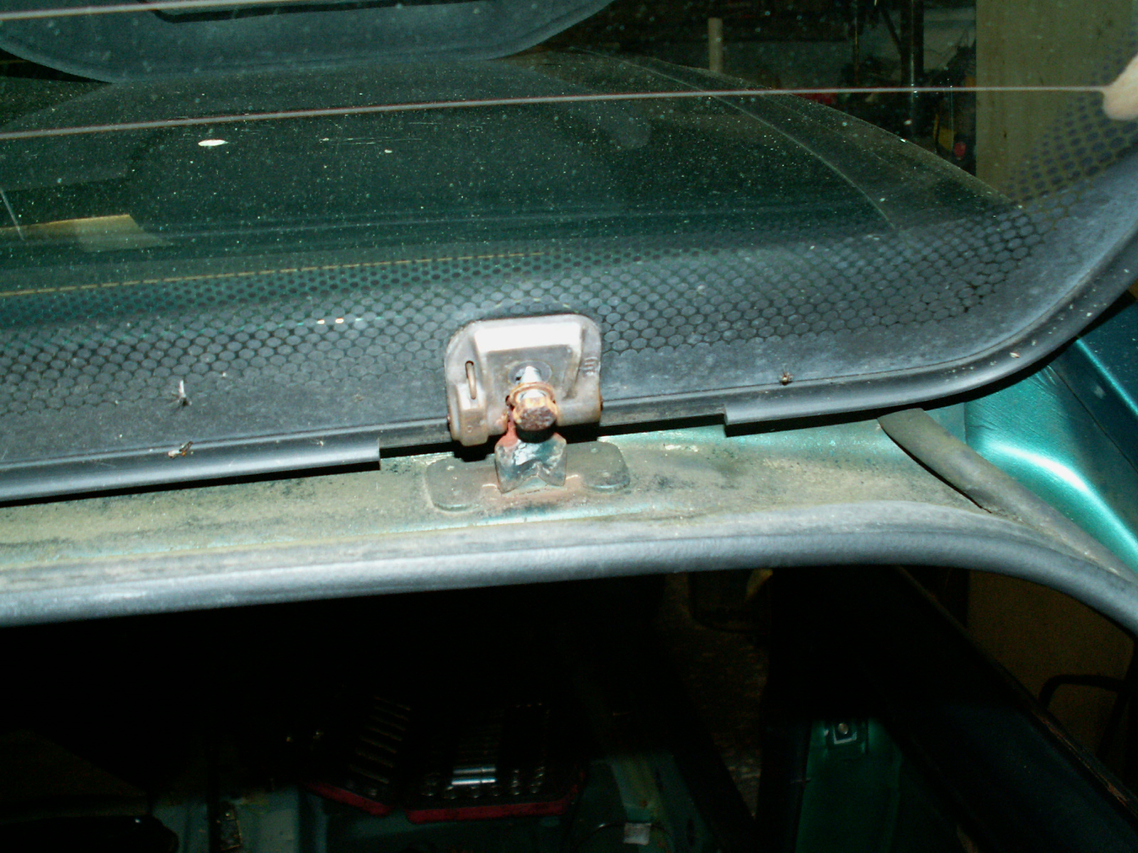
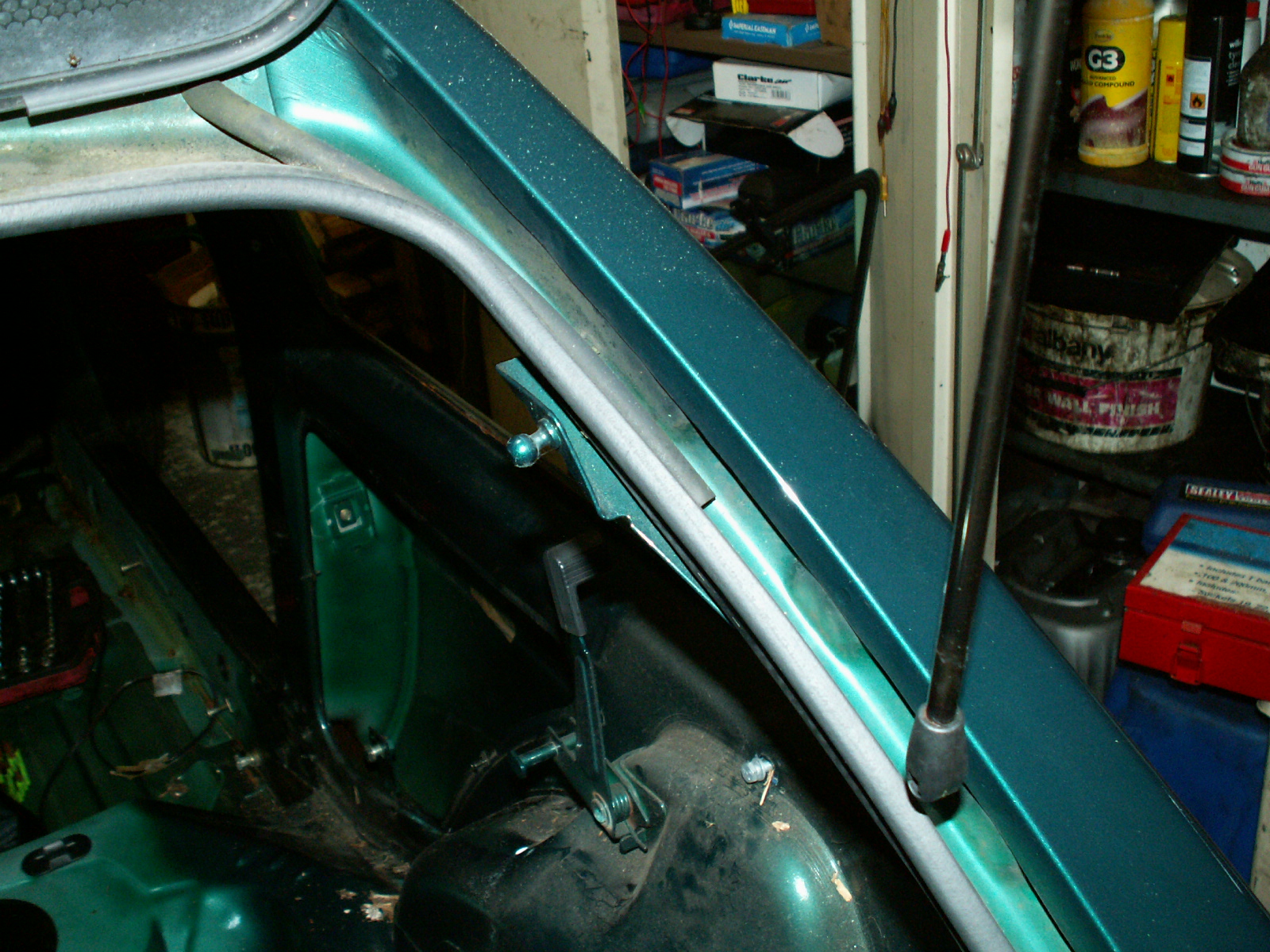
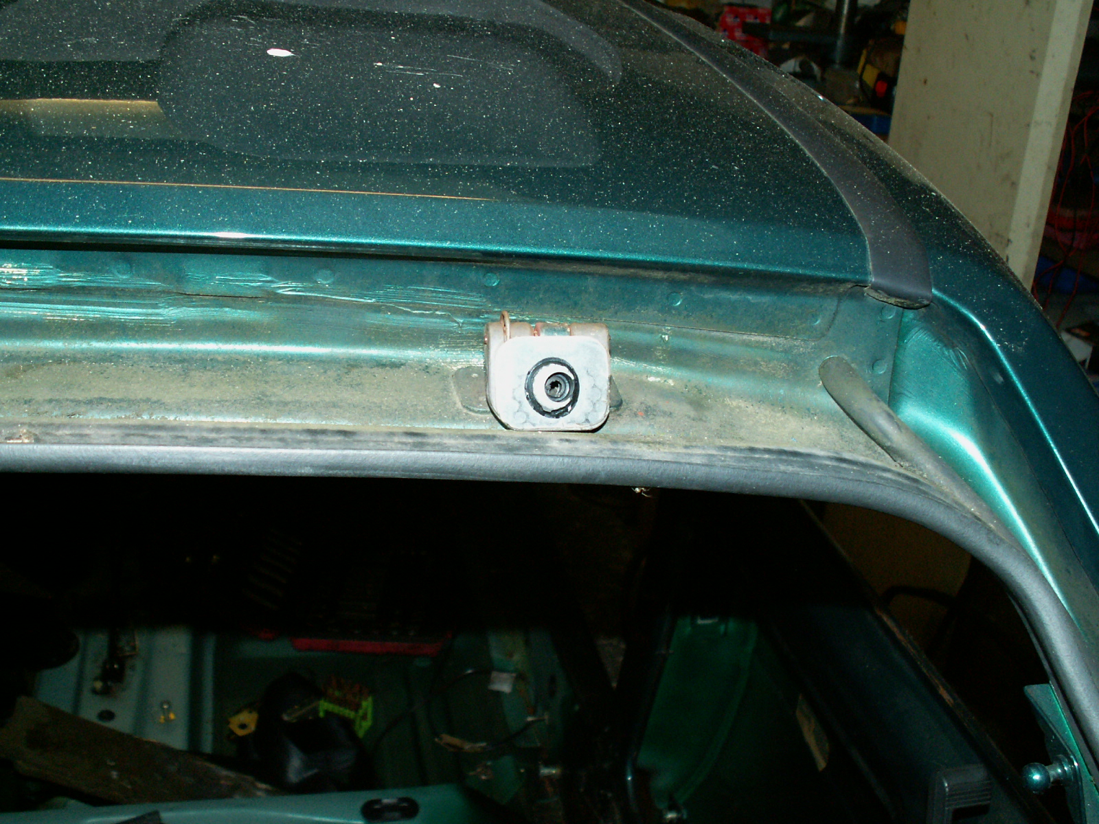
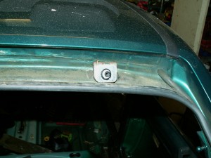
47. Undo the M10 bolts on the two hinges on the tailgate. Take the weight of the tailgate.

KONICA MINOLTA DIGITAL CAMERA

48. Unclip the ends of the two struts, then lift the tailgate off. The hinges are stuck to the glass with mastic but they will separate with a little bit of pressure.

KONICA MINOLTA DIGITAL CAMERA

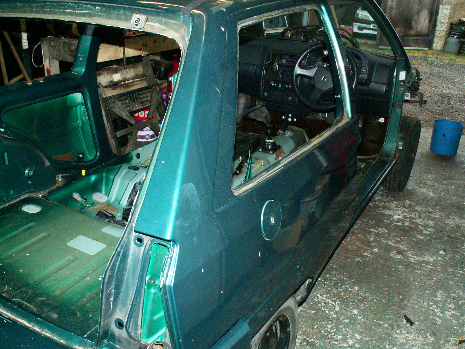
49. Tail gate removed, now pull off the rubber as well.

KONICA MINOLTA DIGITAL CAMERA


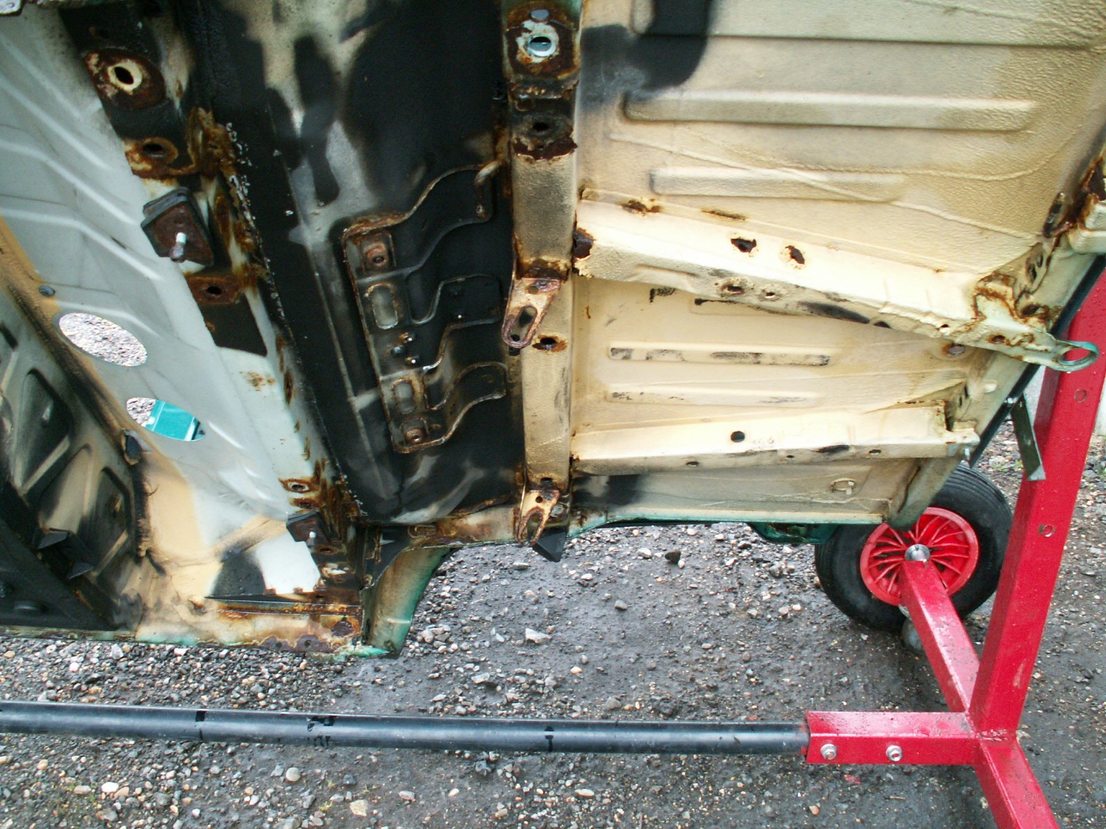
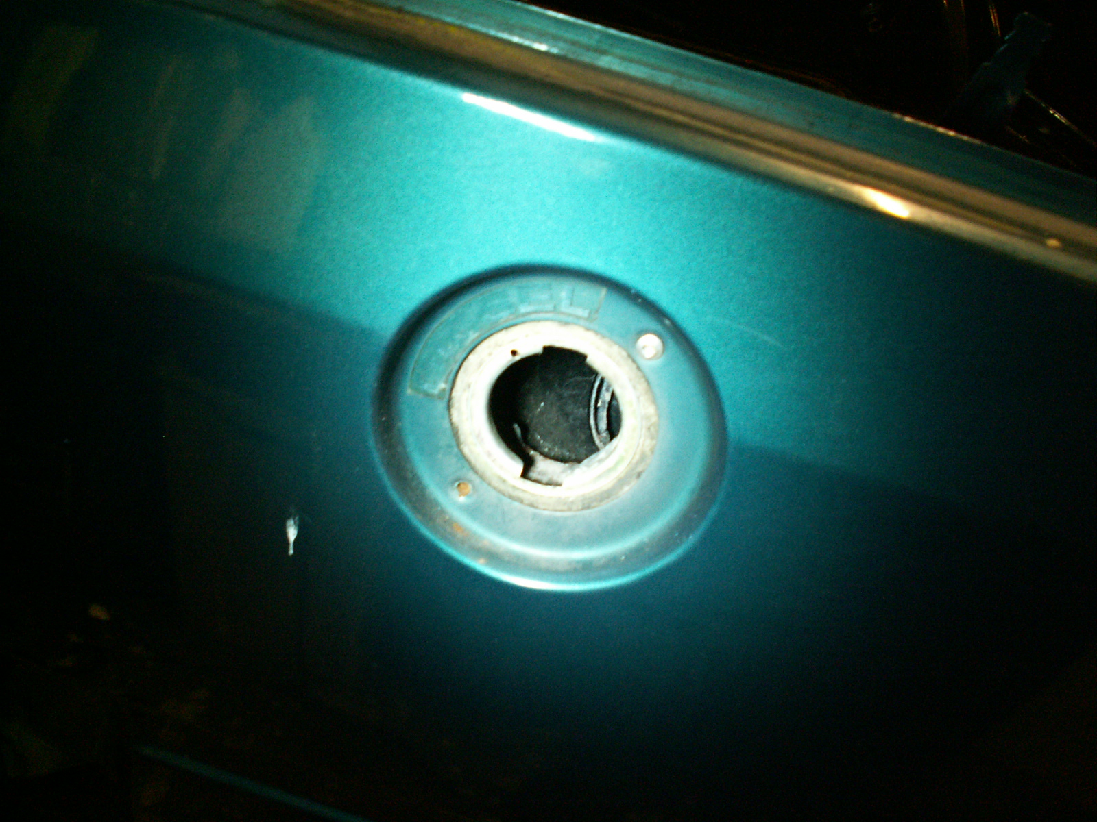
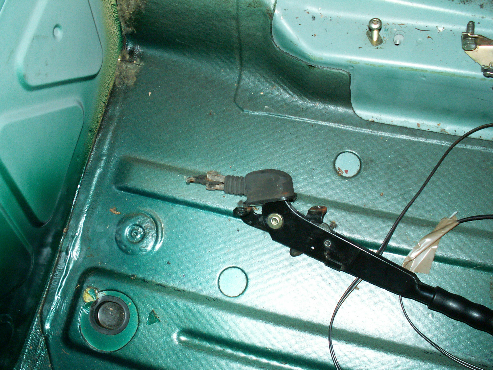
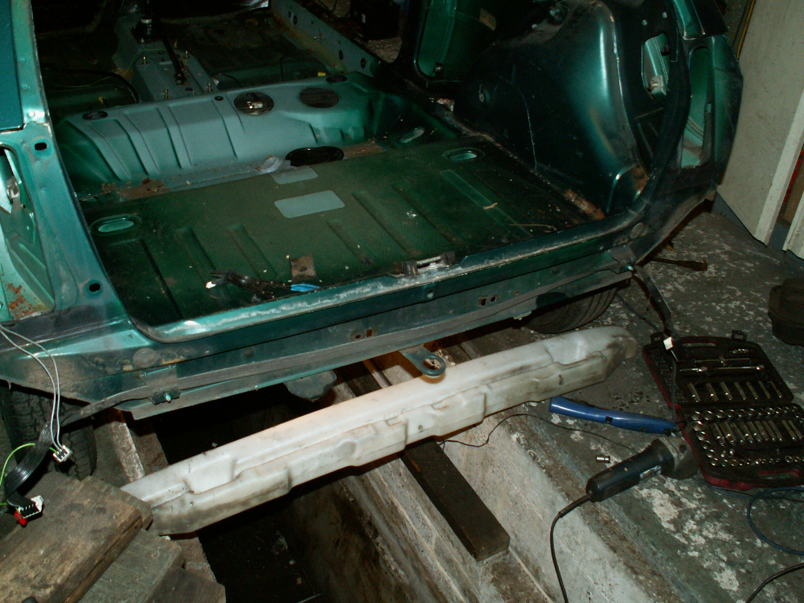
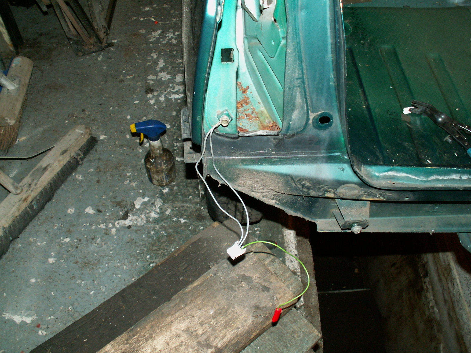
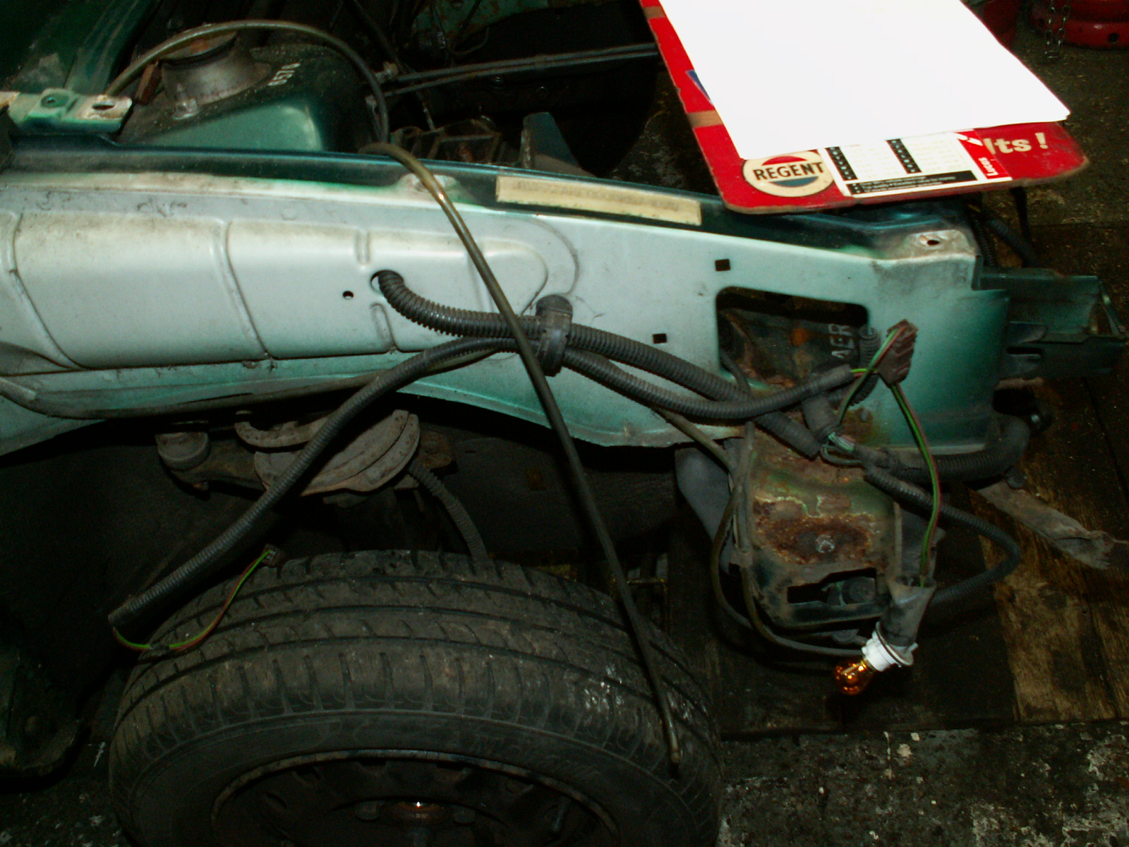
50. Feed the cable back through the car and over the wheel arch and finally pull it from the sill inside the car, this ensures the wires won’t get melted when I weld up the sills!

KONICA MINOLTA DIGITAL CAMERA

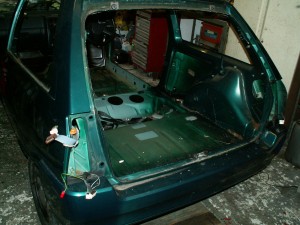
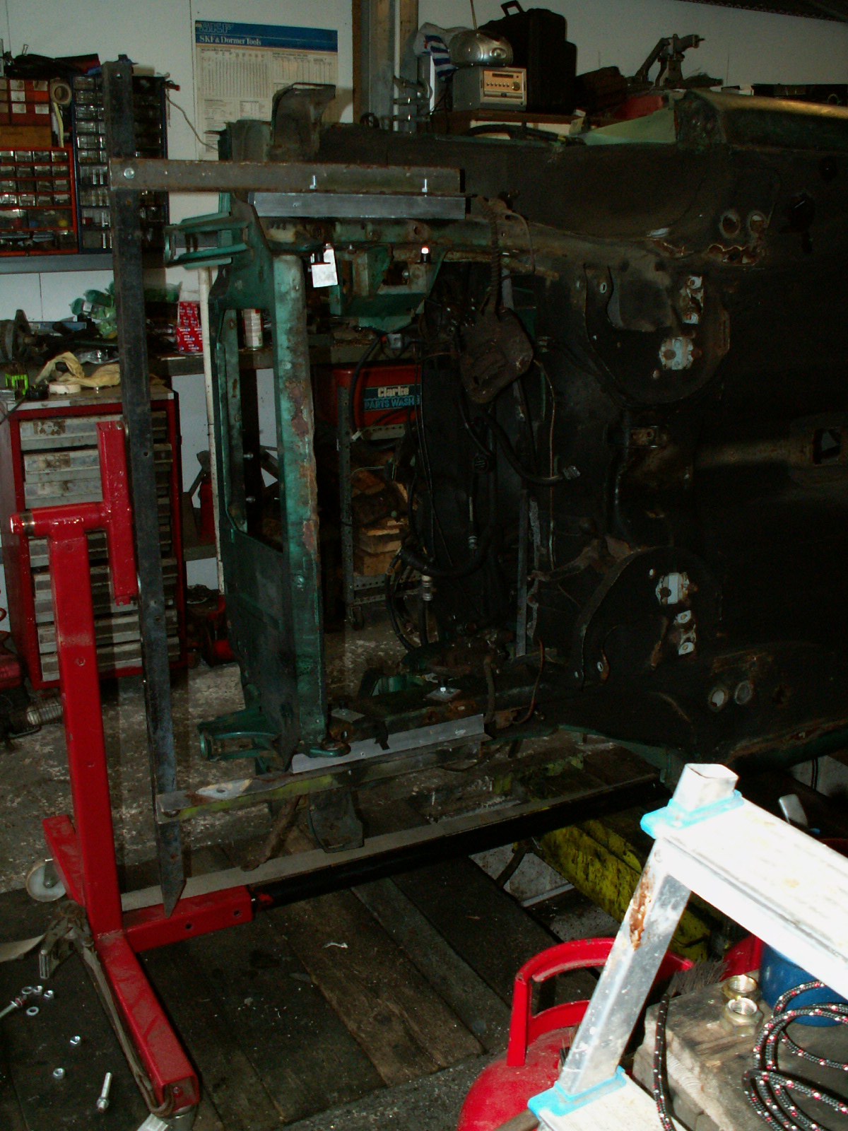
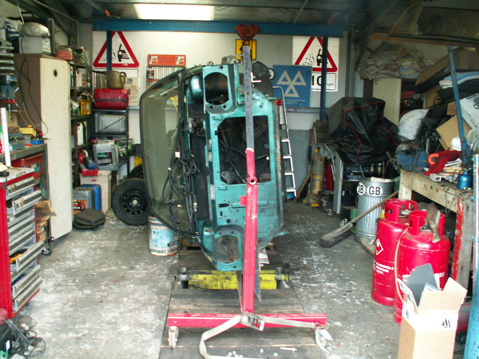
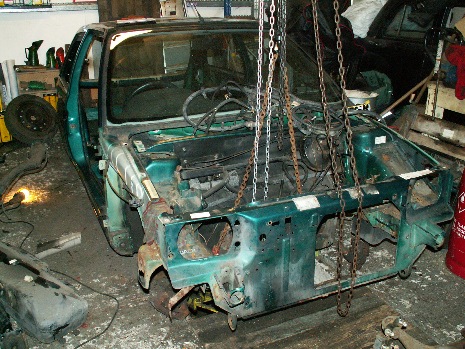
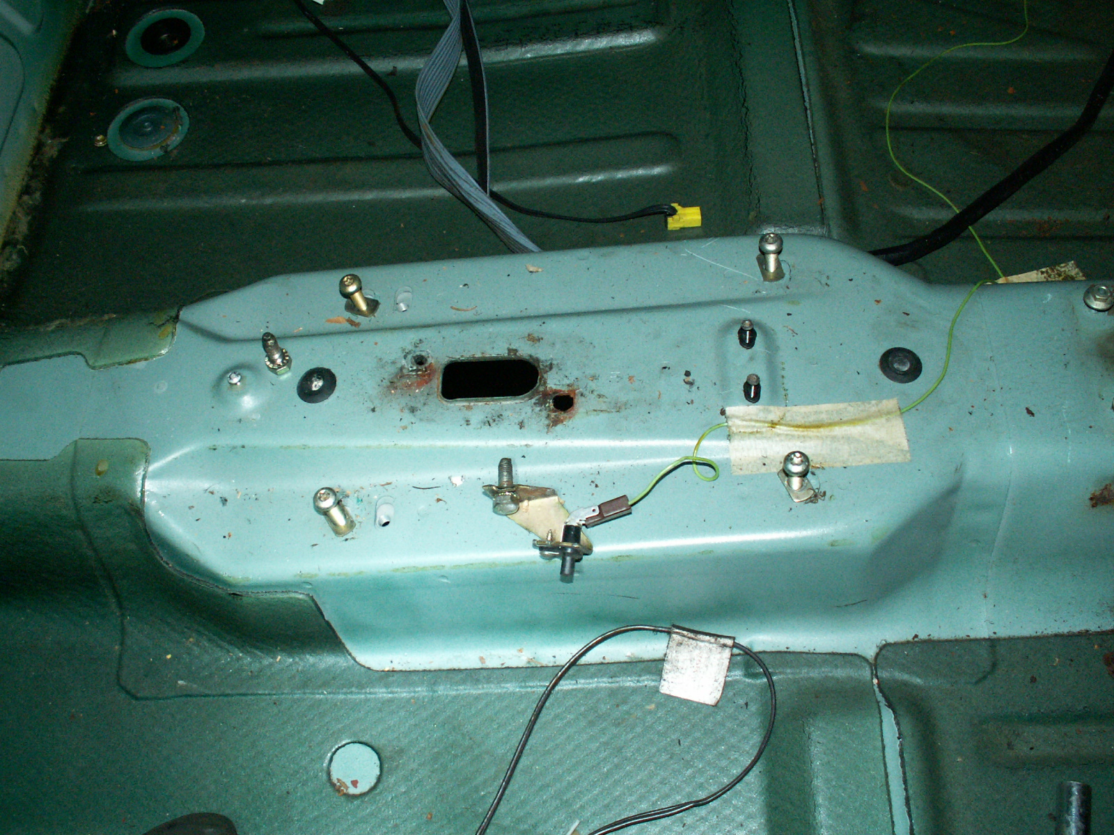
51. Nearly stripped and ready!

KONICA MINOLTA DIGITAL CAMERA

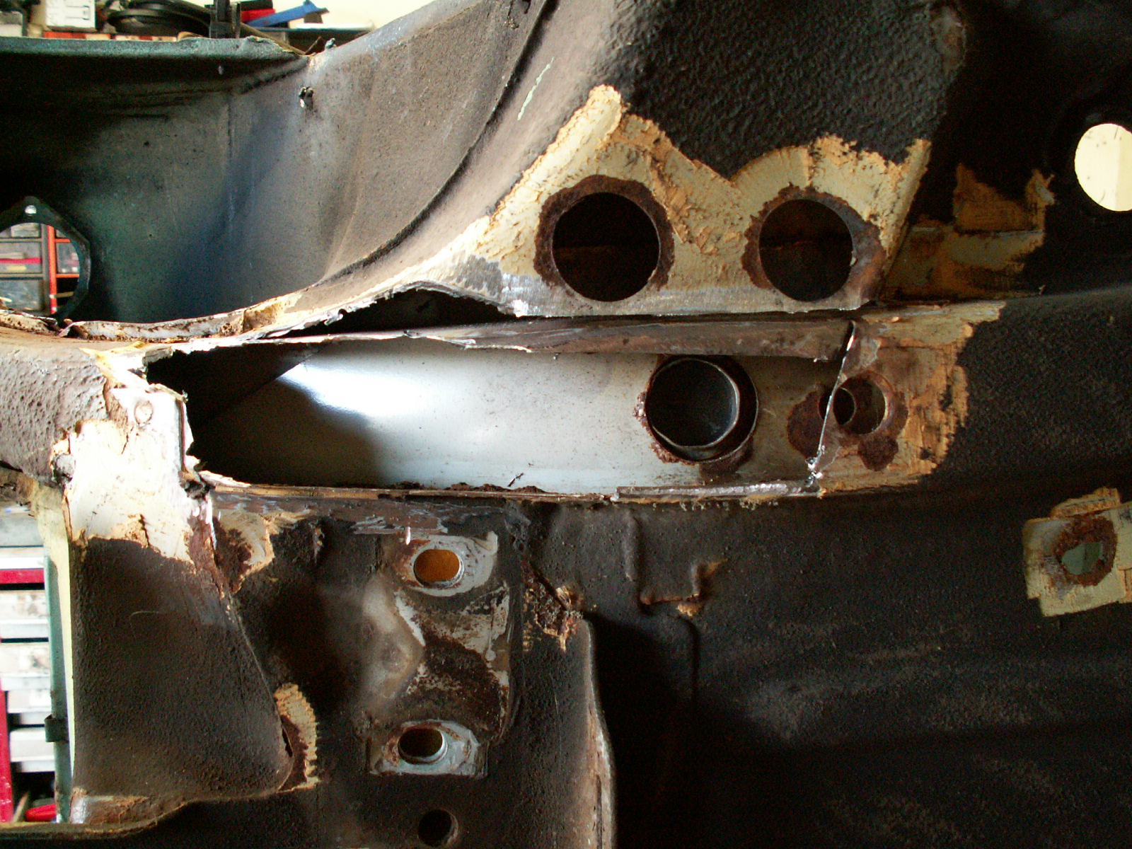
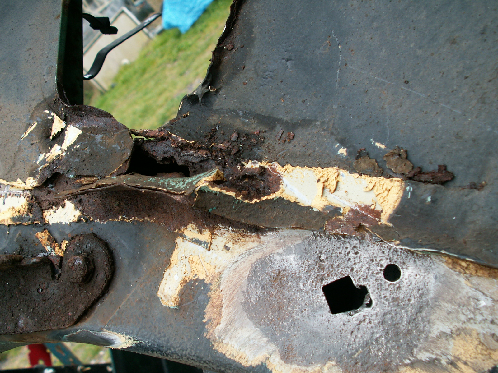
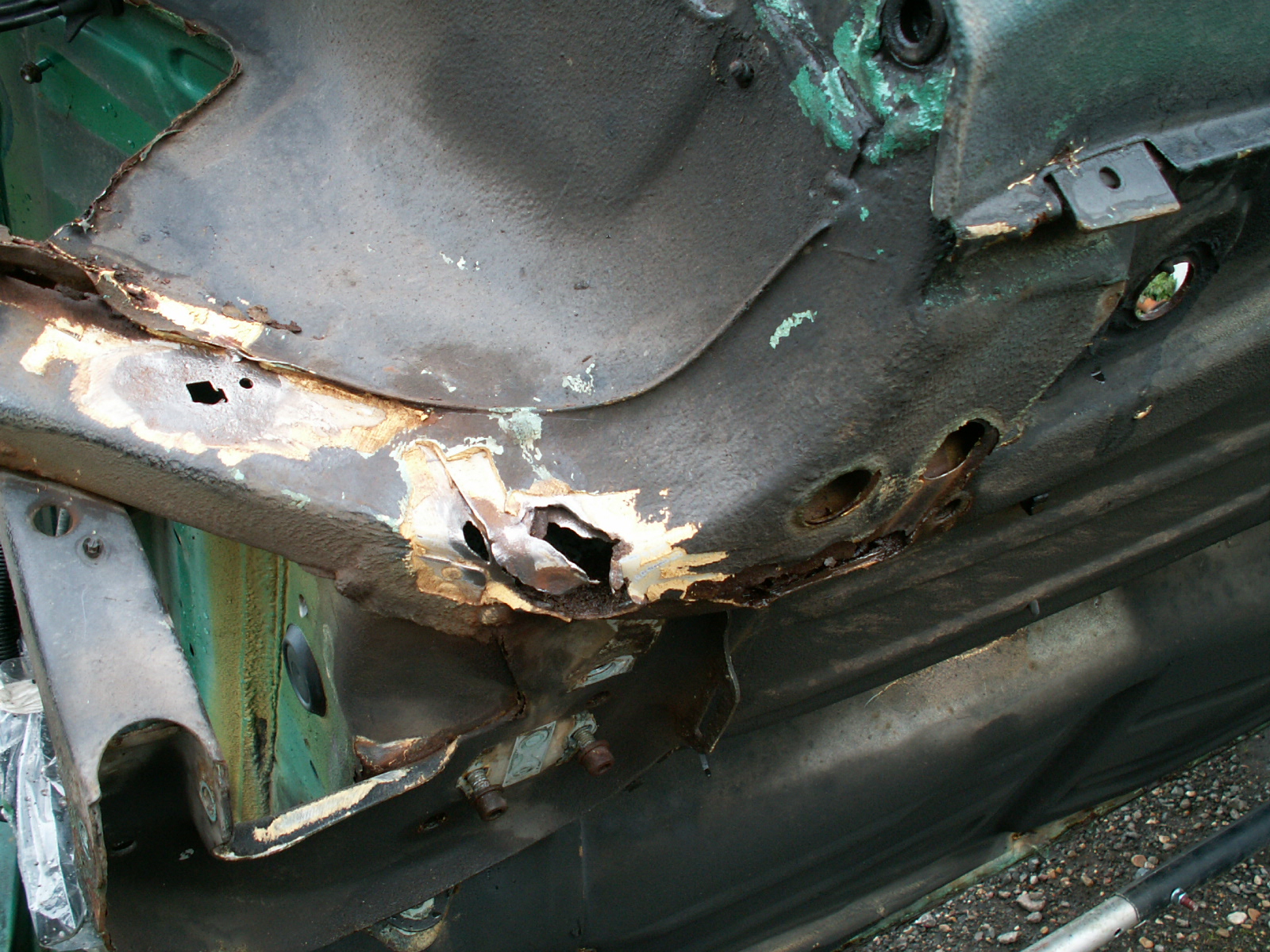
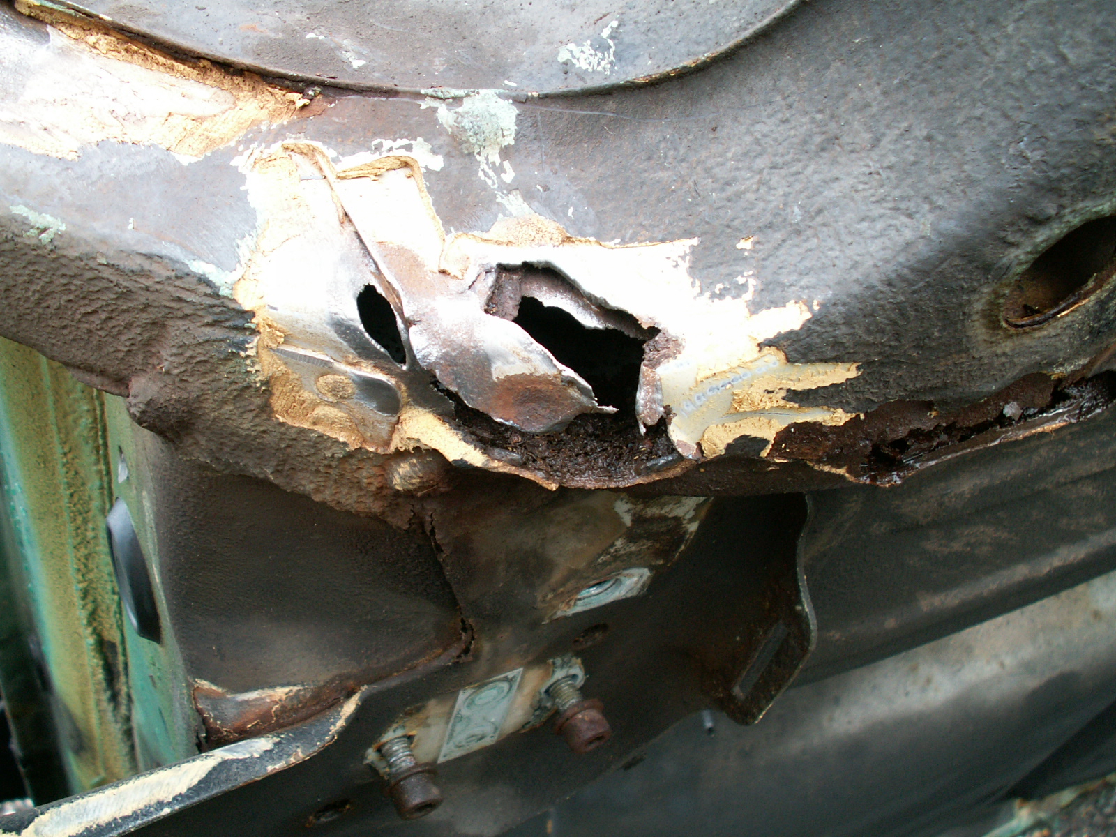
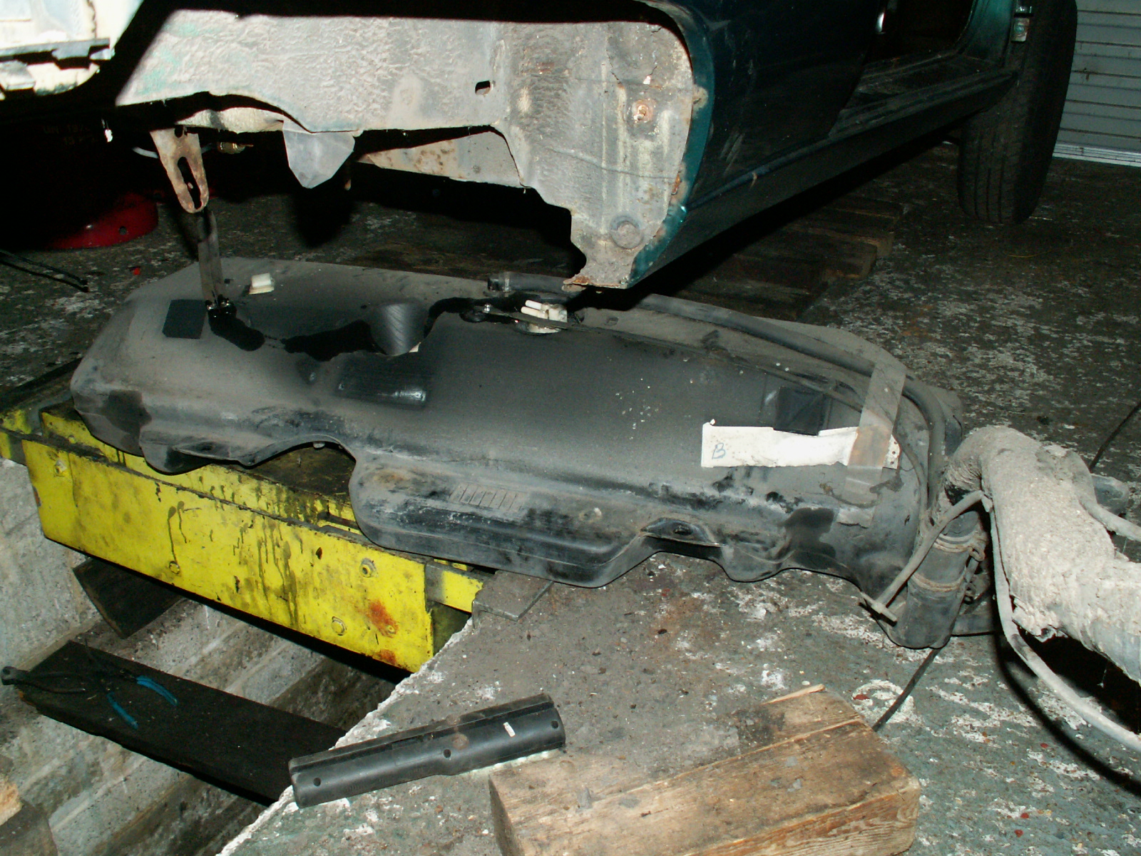
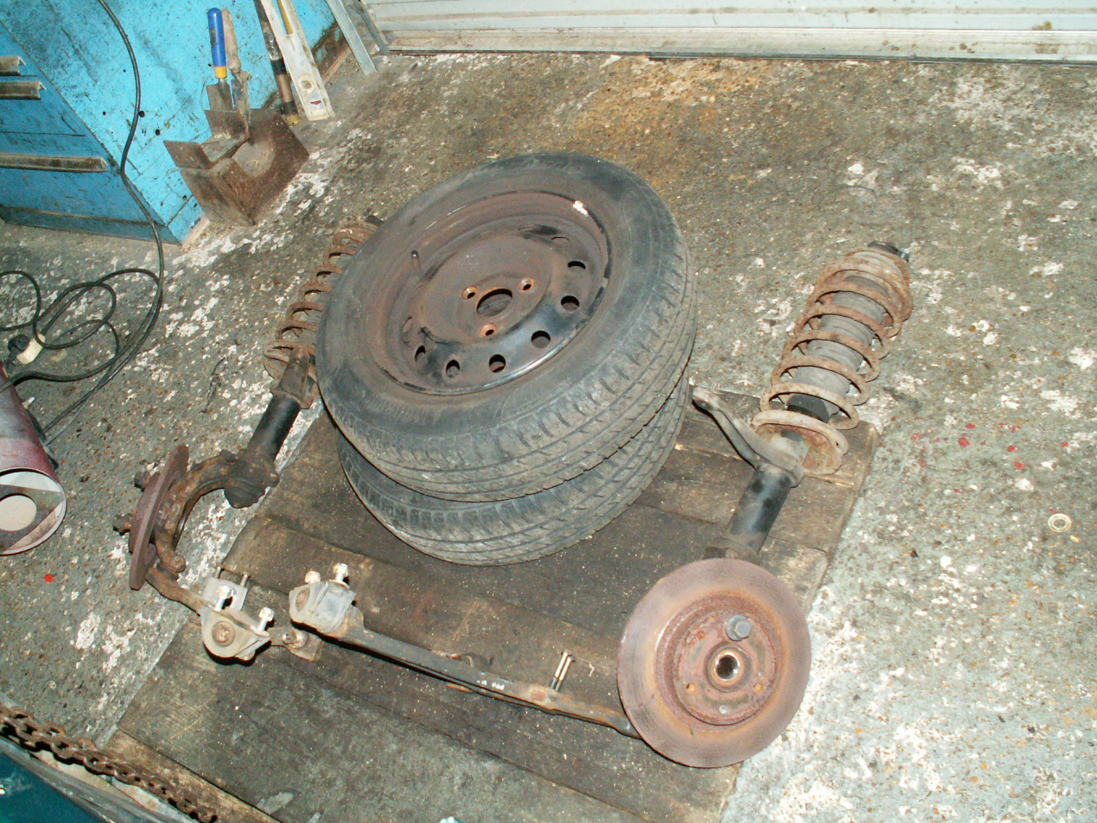
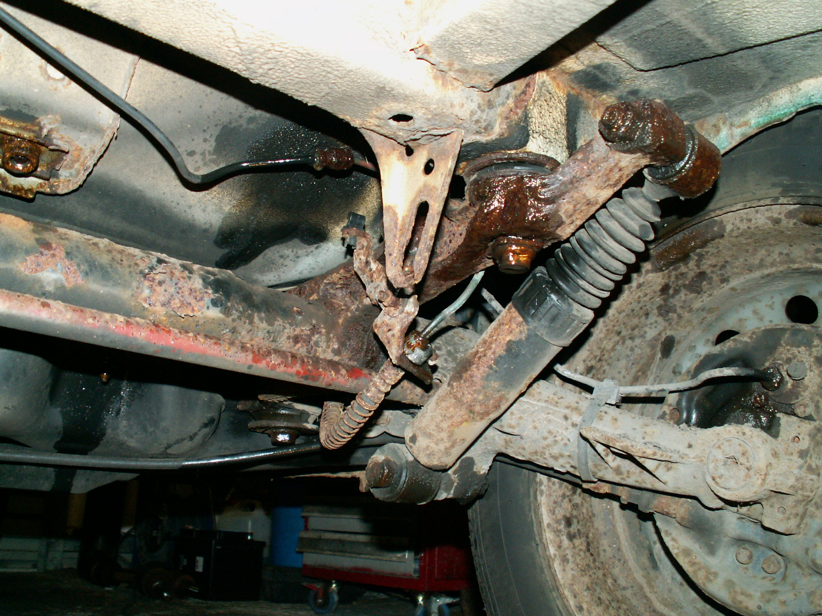
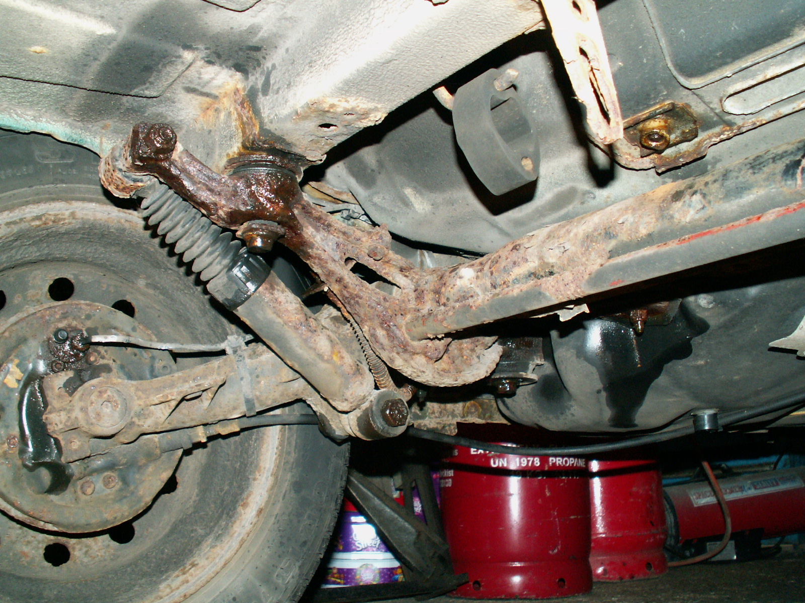
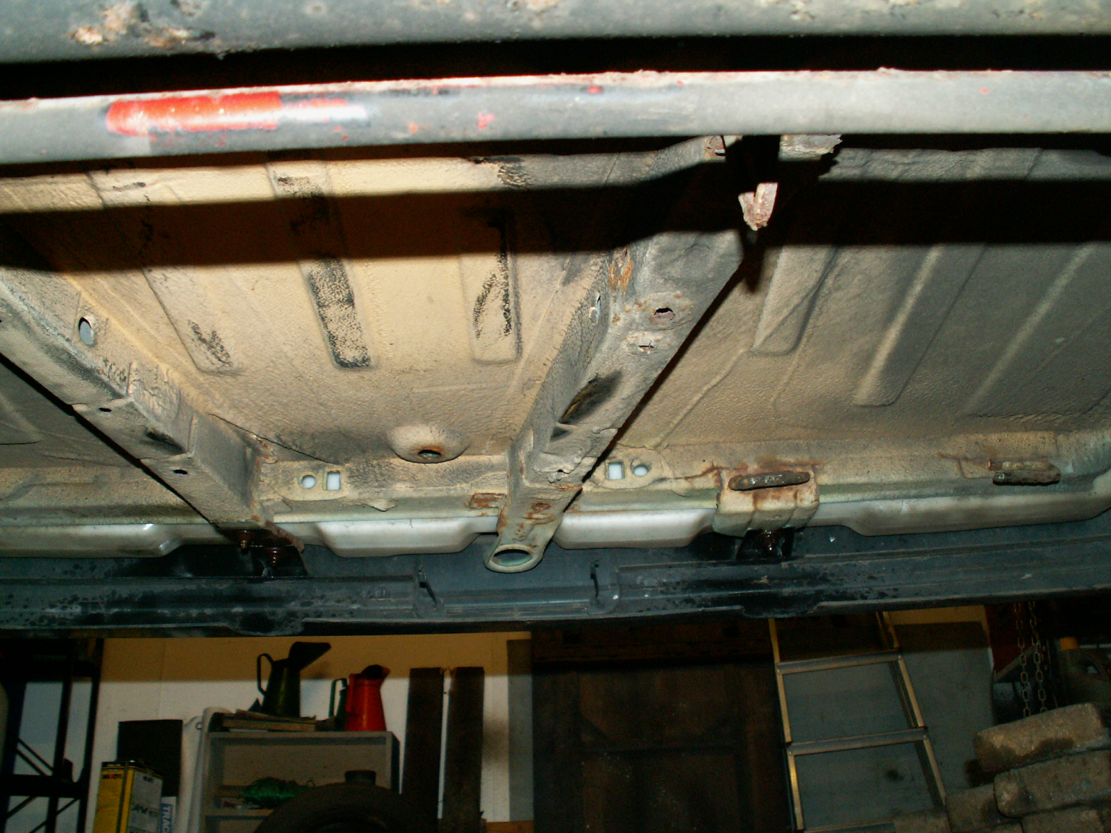
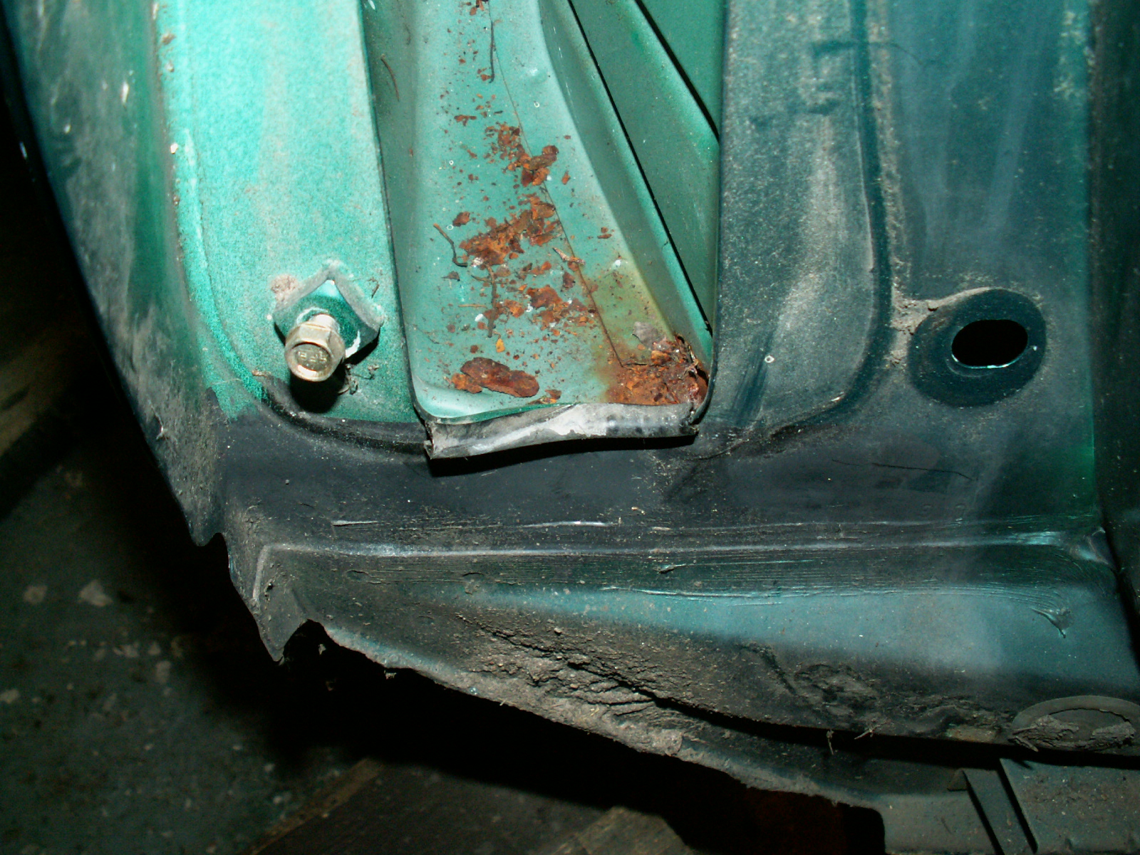
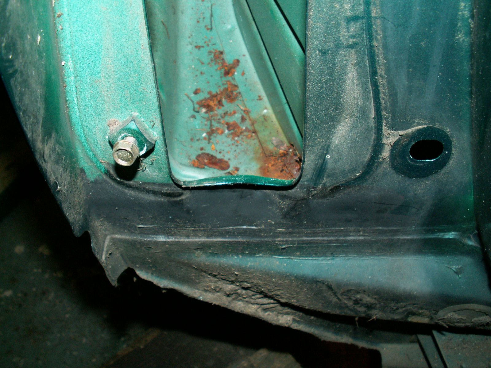
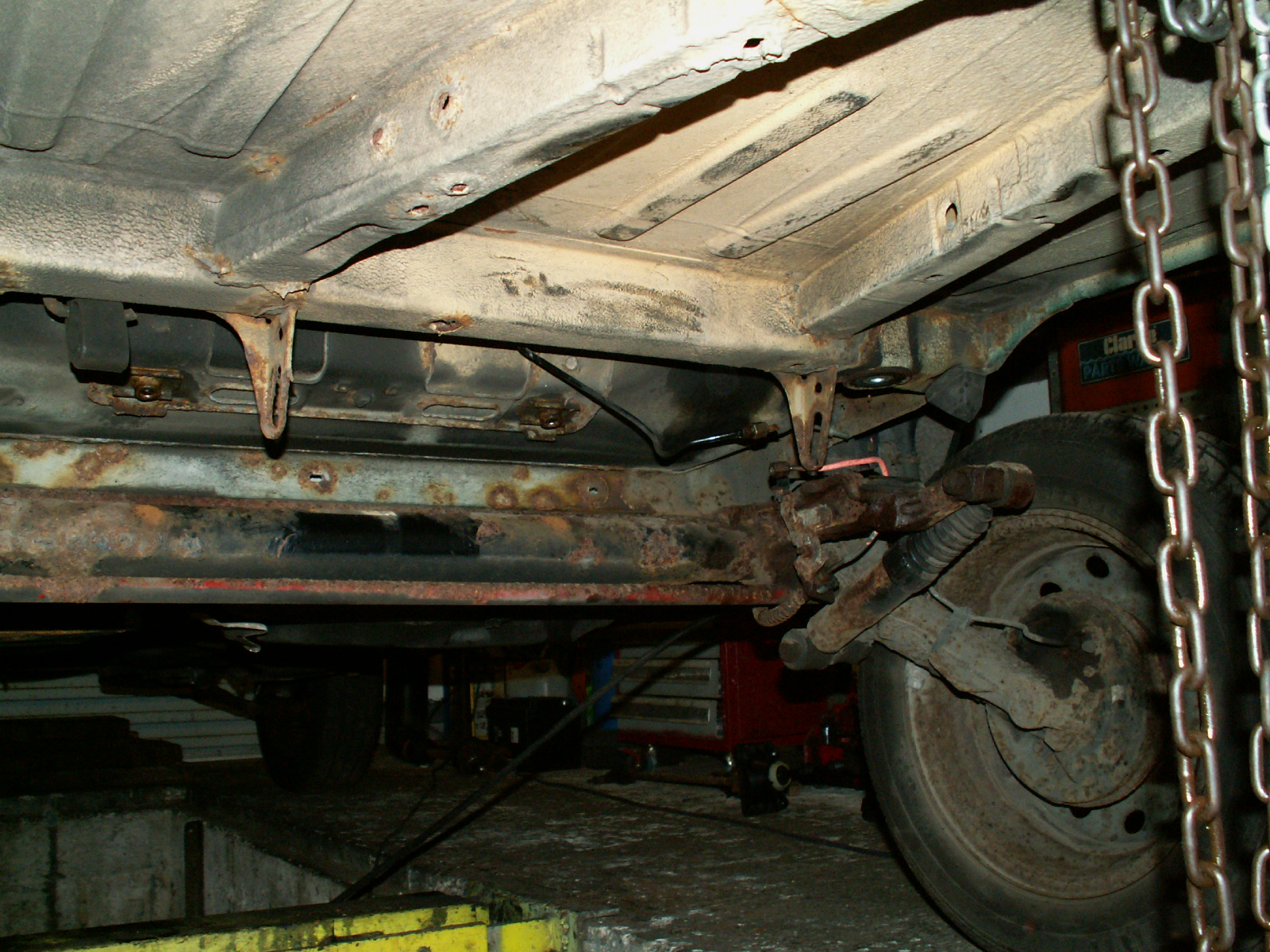
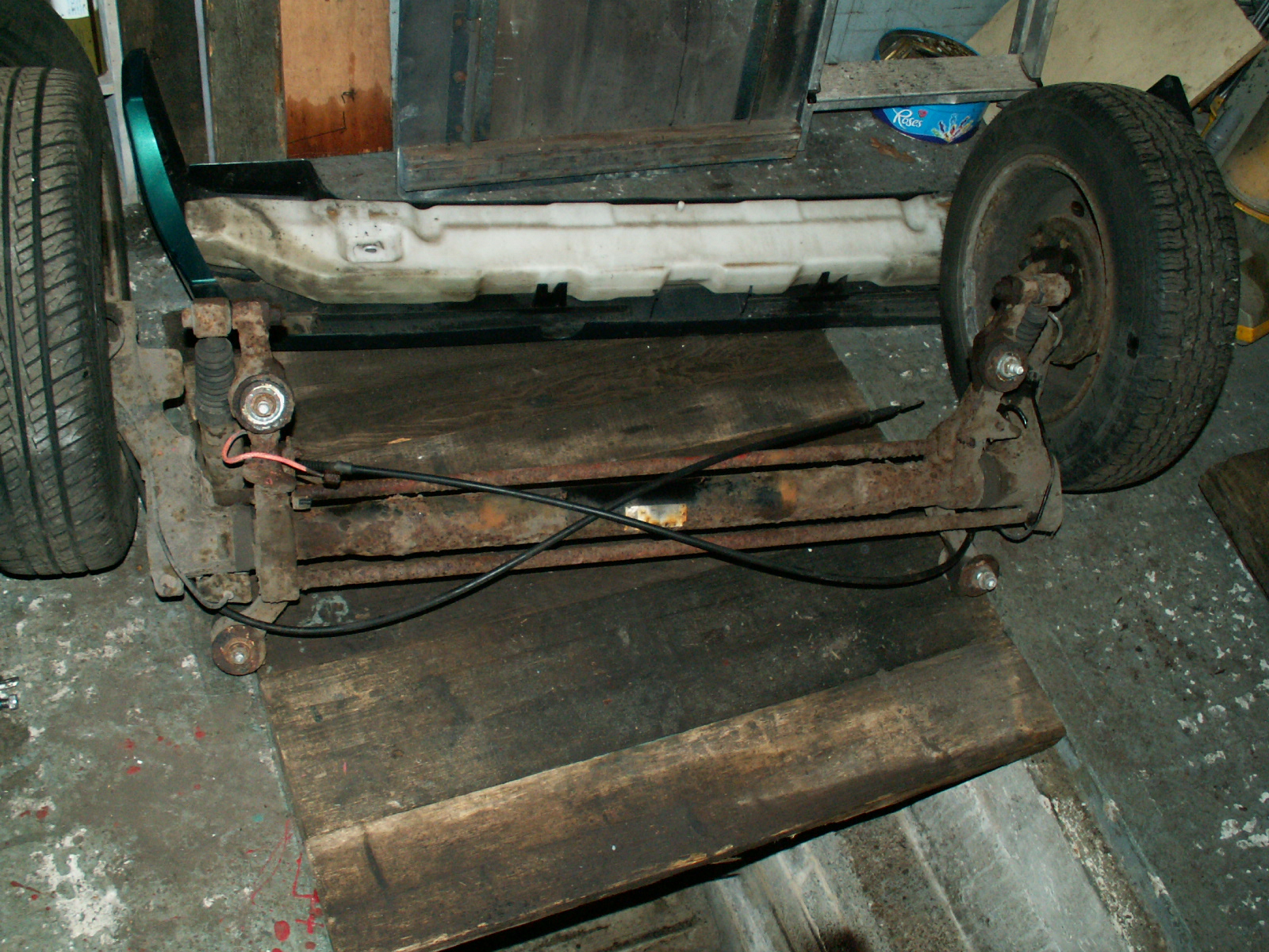
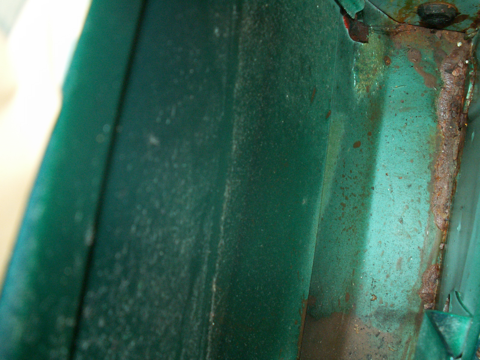
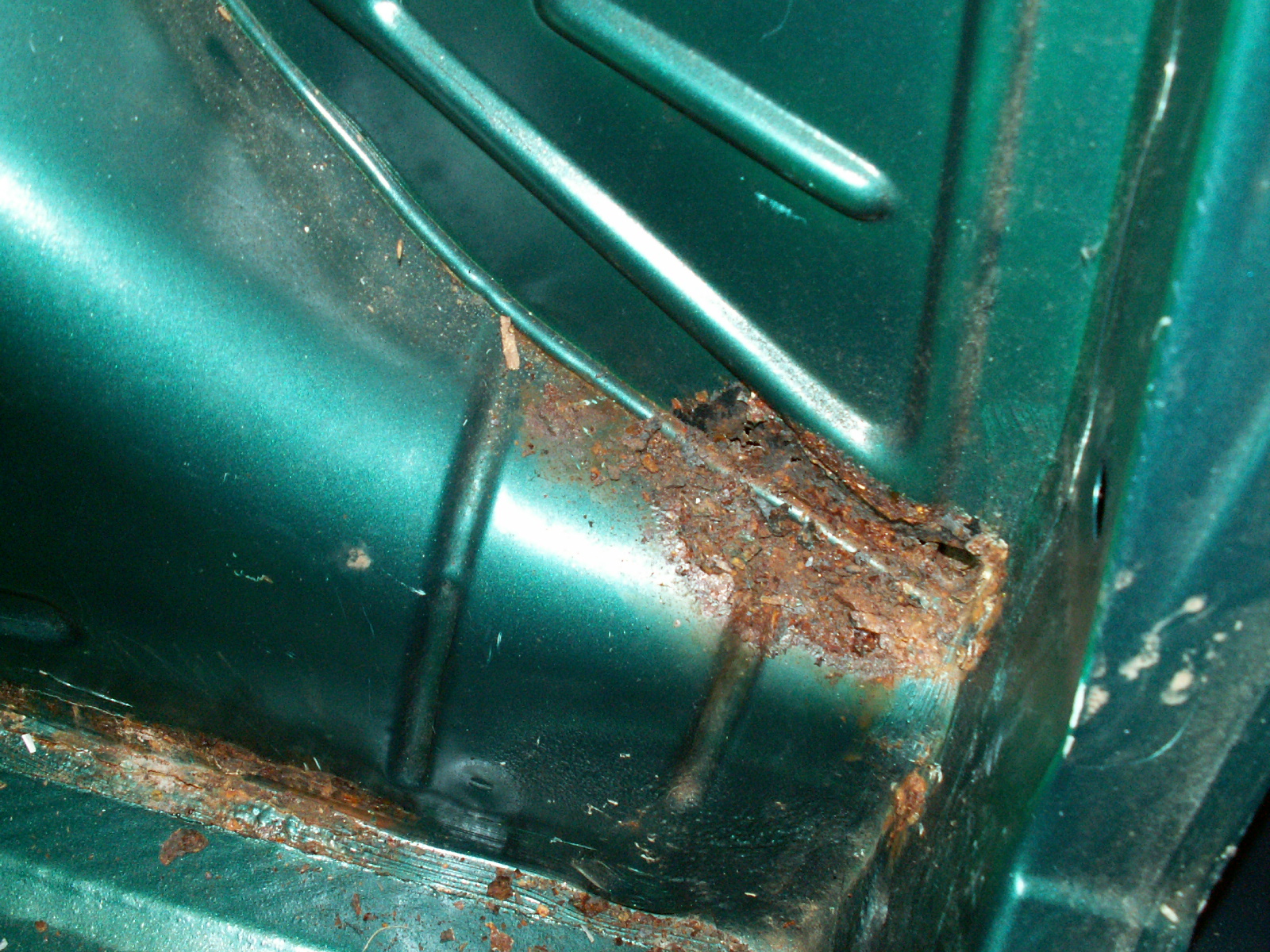
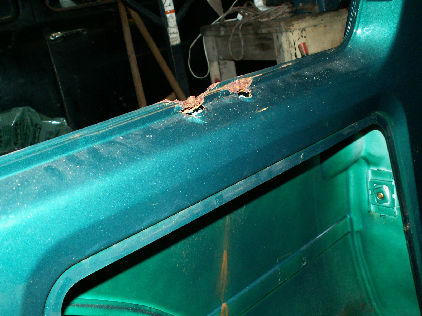
That about concludes the strip down on the inside. I can now see all of the rust – well all that except that underneath! See the next post for pics. Just the rear beam, fuel tank and front struts to remove to get the shell ready for welding.

Citroen AX – The Strip Down – Engine Removal First

Having decided the resurrection of this AX was viable the next step is to remove the engine. I did consider leaving it in but access to some of the rust that needs sorting on the inner wings would be difficult with the engine in place. I also suspect the head gasket is leaking and it is easier to replace and also change the cambelt with the engine out, I can also split the gearbox off and check the clutch.

So, step1….


2015-03-14 15.23.40

1. Start at the front and work back! As It is a complete strip down I am removing everything, so start with the plastic radiator shroud, held in by 4 plastic press fasteners. Whilst we are on easy bits undo the jubilee clip holding the air intake hose on to the air filter box. Unclip from the inner wing and remove.


KONICA MINOLTA DIGITAL CAMERA


2. Next unbolt the bonnet catch from the slam panel, (2 x 13mm bolts).

KONICA MINOLTA DIGITAL CAMERAKONICA MINOLTA DIGITAL CAMERA


3. The remove throttle cable, simply remove spring clip, free the nipple and withdraw, remember to replace the spring clip on the cable so it doesn’t get lost.

KONICA MINOLTA DIGITAL CAMERA

4.  Now onto the radiator. First undo the single 10mm bolt at one end of the fan unit, Slide the fan unit to the right and remove. I found it easiest to drop the fan unit down and remove underneath. You also need to unplug the cable from the fan motor.  Next undo the jubilee clips both ends of the top hose and remove the hose. Unplug the blue connector which is the temperature sensor for the fan.

KONICA MINOLTA DIGITAL CAMERA

5. Then the bottom hose, just visible in the picture below.

KONICA MINOLTA DIGITAL CAMERA

6. Next it is onto the air intake, undo the 4  (might be 5 I can’t remember) screws and the jubilee clip and lift the top of the airfilter housing. The element was filthy so this was thrown away.

KONICA MINOLTA DIGITAL CAMERA

7. Undo the single bolt holding the lower part of the filter housing and simply lift up to remove.

KONICA MINOLTA DIGITAL CAMERA

8. Air filter housing out of the way, now disconnect the heater hose seen here in the centre of the picture.

KONICA MINOLTA DIGITAL CAMERA

9. At the other end we disconnect some more hoses and remove the header/expansion tank.

KONICA MINOLTA DIGITAL CAMERA

10. To gain access to the second bolt holding the header tank you need to unscrew the filler neck of the windscreen washer bottle.

KONICA MINOLTA DIGITAL CAMERA

11. Unclip and free the end of the other heater hose at the back of the engine.

KONICA MINOLTA DIGITAL CAMERA

12. Hoses and tank removed its on to the clutch cable. Use a crow bar to move the clutch operating lever in and the free up the end of the clutch cable.

KONICA MINOLTA DIGITAL CAMERA

13. Remove the last coolant hose from the back of the engine, under the right hand end of the exhaust manifold.

KONICA MINOLTA DIGITAL CAMERA

14.  Now disconnect the multiplug which connects the engine loom to the main wiring loom (just under the servo).

KONICA MINOLTA DIGITAL CAMERA

15. Now disconnect the positive lead that goes off to the starter motor. Access at the starter motor end is restricted so disconnect it at the end which connects to the positive of the battery.

KONICA MINOLTA DIGITAL CAMERA

16.  Now disconnect the diesel flow and return pipes.

KONICA MINOLTA DIGITAL CAMERA

17.  Disconnect the wiring on the passenger side inner wing.

KONICA MINOLTA DIGITAL CAMERA

18.  Finally remove the earth bonding wire.

KONICA MINOLTA DIGITAL CAMERA

19.  Underneath the car remove the rear section of the exhaust by undoing the two spring bolts and removing the rubber hangers. It will easily come off as one piece. There is no need to remove the front pipe from the manifold.

KONICA MINOLTA DIGITAL CAMERA

20. Whilst under the car, “pop” off the three gear linkages. Do this with a 13mm open ended spanner and lever them apart.

KONICA MINOLTA DIGITAL CAMERA

21.  Loosen the bolt on the lower mount. Do not fully remove at this stage, wait until the engine is tied to the hoist. Next remove the rubber “pin” securing the speedo cable to the gear box. This pulls out and the cable can the be lifted up.

KONICA MINOLTA DIGITAL CAMERA

22. Back up top attach you hoist to the two lifting eys at either end of the cylinder head.

KONICA MINOLTA DIGITAL CAMERA

23. Once the hoist has the main weight of the engine remove the two bolts securing the lower middle mount to the gearbox, and also completely remove the other bolt and remove the mount. Take care as the engine may swing backwards a little.

KONICA MINOLTA DIGITAL CAMERA

24.  The underneath of the engine is now free!

KONICA MINOLTA DIGITAL CAMERA

25. Onto the gearbox mount. Undo the two smaller 13mm nuts first.

KONICA MINOLTA DIGITAL CAMERA

26.  Then the larger central bolt.

KONICA MINOLTA DIGITAL CAMERA

27.  Remove the mount. Again take care as the whole assembly may move as the mount is released. Adjust the hoist if necessary.

KONICA MINOLTA DIGITAL CAMERA

28. Last remove the three nuts holding the drivers side mount.

KONICA MINOLTA DIGITAL CAMERA

29.  Once removed the engine is free.

KONICA MINOLTA DIGITAL CAMERA

30. Now the engine is free lower it to the ground, its will only go down! Its too wide to lift up!

KONICA MINOLTA DIGITAL CAMERA

31.  I use a levelling bar to “balance” the weight and keep the engine level on the hoist.

KONICA MINOLTA DIGITAL CAMERA

32.  Use some wood blocks to steady the engine when it is on the floor. You now have to use the hoist to lift the car over the engine!

KONICA MINOLTA DIGITAL CAMERA

33.  Use a chain (or rope) around the inner wishbone mounts to lift the car.

KONICA MINOLTA DIGITAL CAMERA

34.  Keep lifting the car until it clears the top of the engine – needs lifting around 2 feet (600mm).

KONICA MINOLTA DIGITAL CAMERA

35.  Once clear the car can be rolled back clear of the engine.

KONICA MINOLTA DIGITAL CAMERA

36.   Car and engine are now divorced!

KONICA MINOLTA DIGITAL CAMERA

37.  Now the engine and gearbox can be lifted onto a trolley to move them out of the way.

KONICA MINOLTA DIGITAL CAMERA

38. I made a trolley out of 4 castors, four bits of dexion angle and a bit of old worktop.

KONICA MINOLTA DIGITAL CAMERAKONICA MINOLTA DIGITAL CAMERAKONICA MINOLTA DIGITAL CAMERA

39. Once on the trolley the engine was secured by bolting a couple of bits of dexion angle between the trolley and the alternator mount and another to one of the gearbox bell housing bolts. Saves the problem of the engine tipping over and  breaking your leg!

KONICA MINOLTA DIGITAL CAMERA

40. So here it is, engine and gearbox removed, doing a twirl on the custom trolley.

KONICA MINOLTA DIGITAL CAMERA
KONICA MINOLTA DIGITAL CAMERA KONICA MINOLTA DIGITAL CAMERA

41. Next ……. strip the rest of the car to get to the rust!