
Having spent so much time over Xmas “playing” with the 3D printer it came to my attention that the woodshed is starting to look a bit bare – the cold spell last week “swallowed” a big chunk of the wood reserves! so thoughts turned to finishing the work on the Lister.
Yesterday afternoon I set about cleaning up all the metal work and fuel tank. Usual procedure – aggressive wire wheel on the mini angle grinder ( goggle people – those bits of wire really do dig in!) to clean off all the old paint and rust. Then a quick coat of what ever I have lying around in either a tin or rattle can (aerosol paint tin to the uninitiated). All was well until I got to the tank, 3 rust holes in the base of it – I assume its where the diesel floats on top of any water in the system, so the water rots out the bottom of the tank. Anyway, no problem I though – I have a spare engine somewhere, I’ll pinch the tank off of that, it’s been dry stored for years it’ll be OK. Well 15 minutes later after I had found the engine, moved it to where I could get at the tank and the removed the tank I found it had no bottom at all! – Back to square one. The solution was to clean up the base really well removing all traces of rust and then tin and solder the holes. Years ago I got a car body soldering kit for lead loading bodywork. It consists of a really aggressive flux, some tinning butter and some thick sticks of solder with a wide paste temperature range. Worked like a dream, I coated the whole bottom section.
Next repair job was on the ducting plates that direct the airflow around the cylinder, When I removed them I found four of the fixing tabs had snapped off. 5 mins with the gullotine and spot welder saw new tags fitted. Everything was then sprayed up and left to dry.
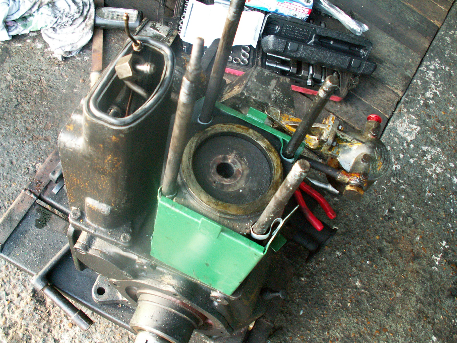
Next up setting the cylinder head clearance – I had already cleaned the head, removed the valves and reground the seats etc. They really were in quite good condition so only a light grind was needed. To measure the clearance between the head and the piston you lay a thin piece of lead on top of the piston, fit the head, turn the crank to push the piston over top dead centre, then remove the head and measure the thickness of the lead. Not having a suitable piece of lead I used four bits of multicore solder twisted together to make a bit of lead “rope” – worked really well. The clearance was 1.06mm. so I ended up removing the copper gasket at the base of the cylinder and double checking that there were no burrs anywhere. When rechecked it was 0.8mm, just in tolerance.
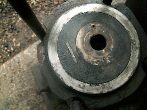
“Squashed” solder rope!
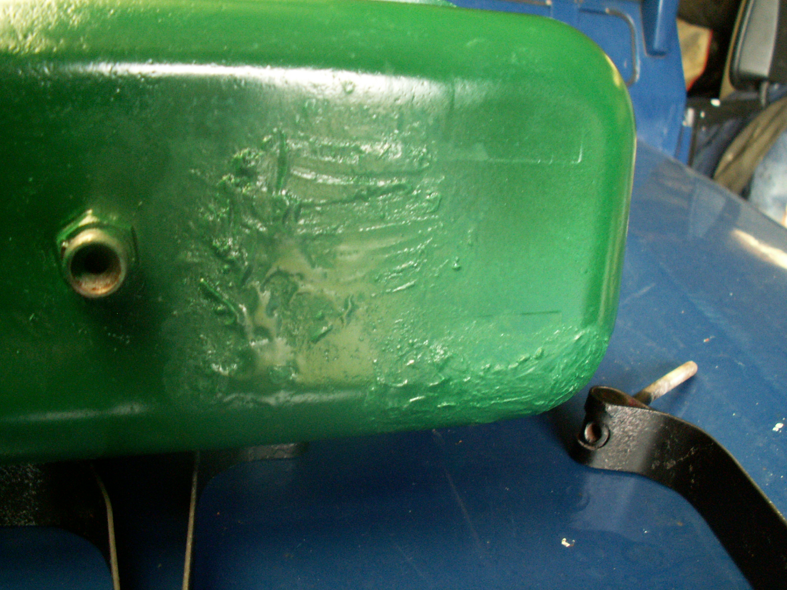 Tank cleaned, soldered and painted.
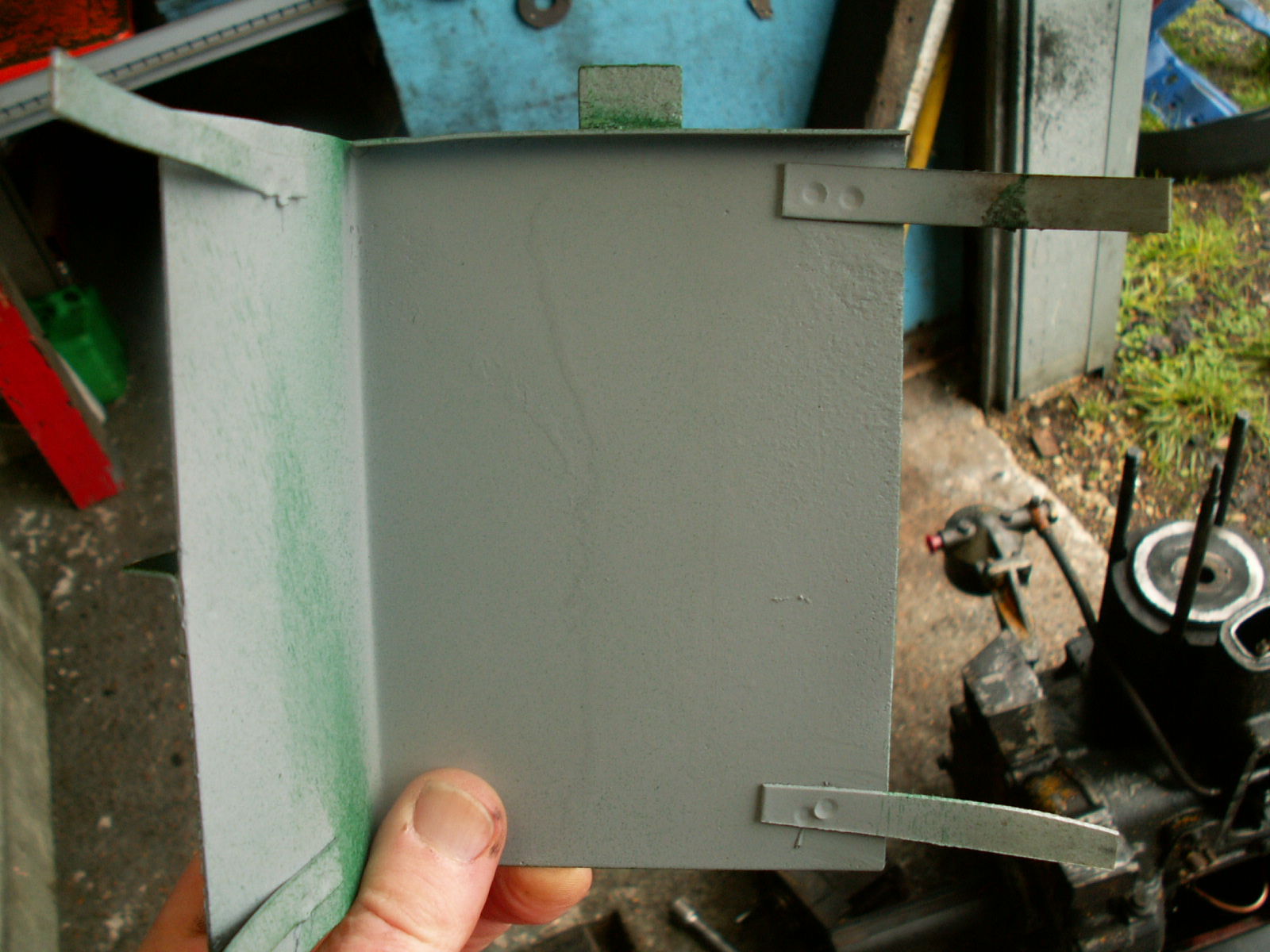
Duct panel with new fixing tags spotwelded on.

Tank looking like new – paint was still soft so the diesel took some of it off again!
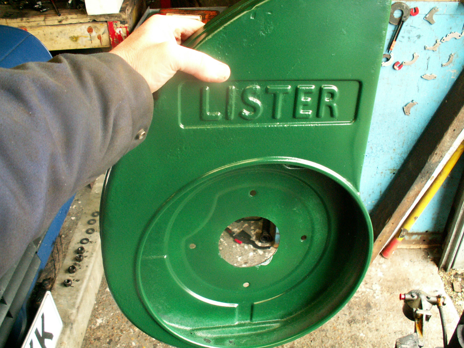
Fan cover ready to go back on.
Cylinder and duct covers fitted.
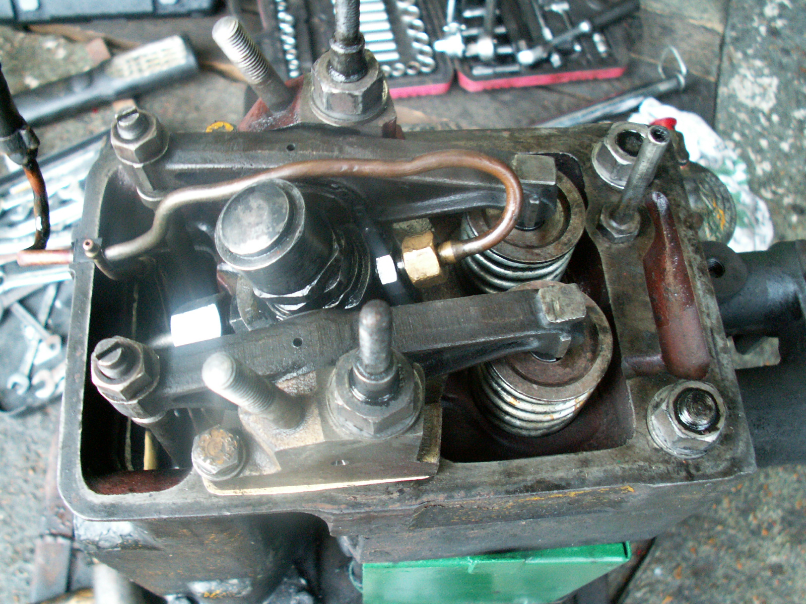
Head, injector & rockers fitted.

Nearly there, rocker cover, fan cowl and manifold fitted.

Ready for the flywheel, airfilter and silencer!
More soon!