All posts by marshman

Citroen AX 1.5D ……. Front Wheel Bearing Replacement.

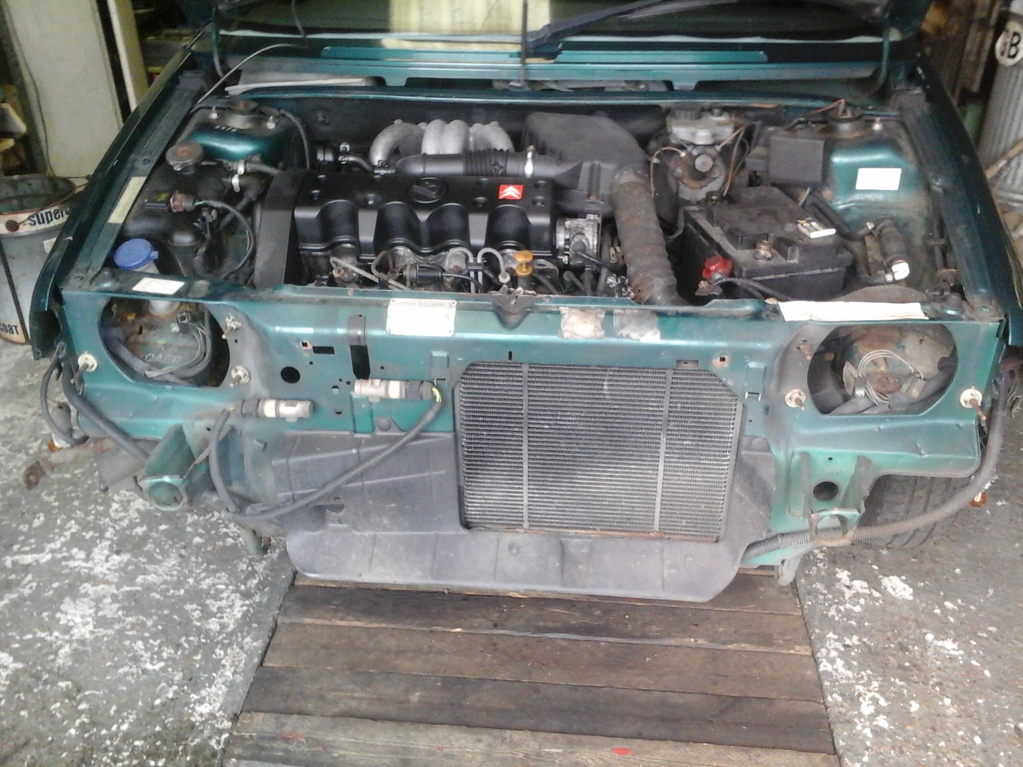
The first main task in getting the AX back on the road – or at least seeing if it is worth the effort of getting it back on the road – is to get to the bottom of the grinding noise. The noise is present at any speed, is road speed related and is load enough above a few MPH to drown out the diesel engine. It almost disappears when turning – even gently – right and gets a lot worse or harsher when turning left. This made me think a) front wheel bearing and b) passenger side – (this is based on the fact it gets worse as more weight is transferred onto that wheel).

Pics below show the way I did it – took about 2 hours for the passenger side.

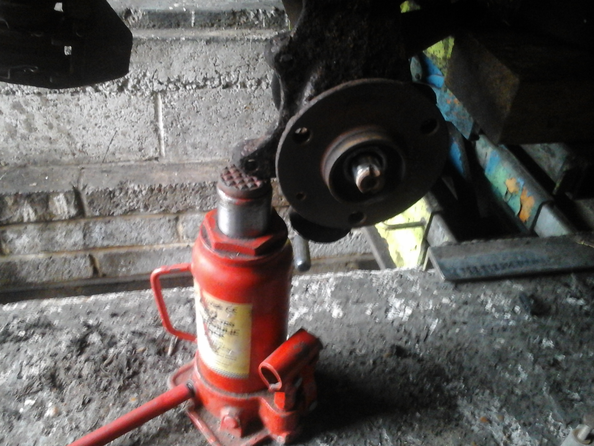
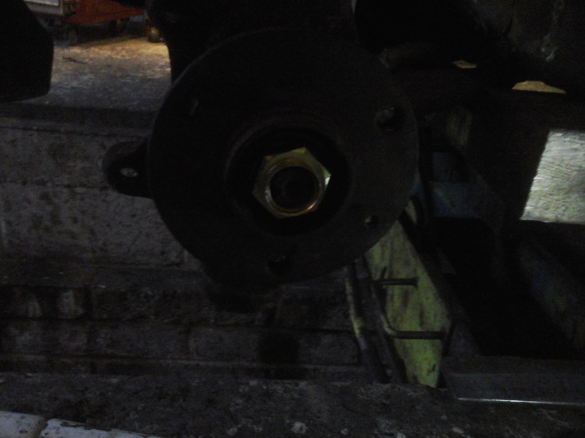
1. Before jacking up the car or removing the road wheel slacken off the hub nut. This is tight! Use a 30mm socket and a 3 foot long bar. You will need to “chock” the front wheel. Make sure you push down and don’t be tempted to pull up as usually you end up lifting the wheel and the wheel spins round – the AX is a very light car!

2015-03-14 16.02.55


2.  Now jack up the car, Lift the entire front and support on axle stands placed under the “Y” pieces under the front foot wells. You need both wheels “hanging” on the suspension to remove any stress/twist from the anti-roll bar. Next remove the road wheel.

2015-03-14 16.15.34


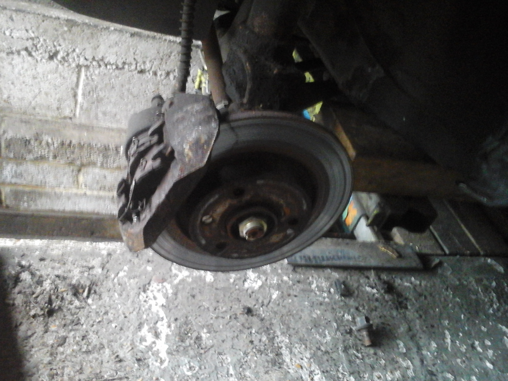
3. Next unplug the brake pad wear indicator wires if fitted then undo the two bolts holding the calliper on, slightly ease the piston back and slide the calliper off. Use a thin bit of steel wire, string, rope or a bungy cord to tie up the calliper to the inner wing. DO NOT LET IT HANG ON THE BRAKE HOSE.

2015-03-14 16.19.19

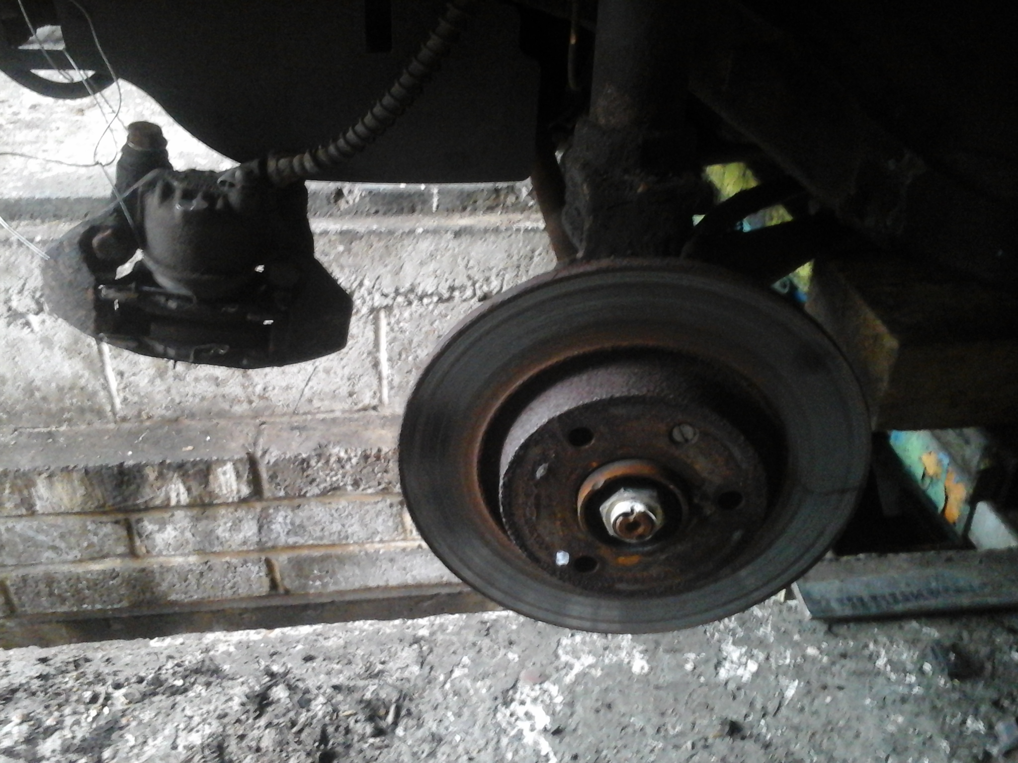
4.  Undo the small torx headed crew which holds the brake disc in place and then remove the disc.  Then use a jack to slightly lift the bottom of the suspension strut, this takes any twist out of the anti roll bar. Next undo the two bolts securing the roll bar to the wich bone. Once the bolts are free lower the jack and the wishbone should come away from the roll bar. At this point also undo the nut holding the track rod end to the strut, Once removed split the ball joint – if you are lucky a light tap from a hammer will free it (take care not to damage the threads – leave the nut on until the joint is cracked), if not either use a ball joint splitter or use two hammers, one resting one side of the strut arm and give the other side a smart crack with the other hammer. This “squeezes” the taper joint and forces it apart – usually! Remove the hub nut.

2015-03-14 16.26.39

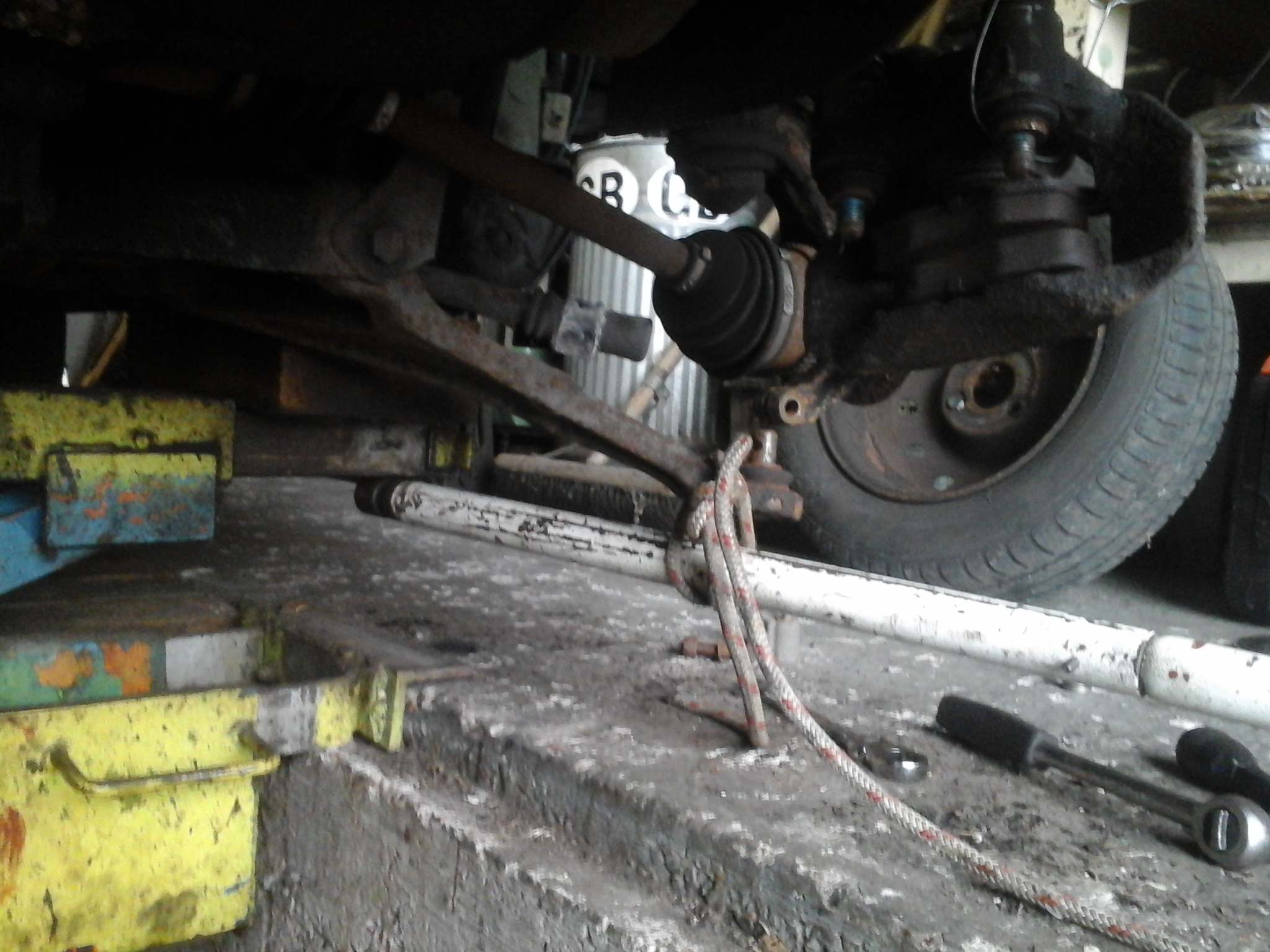
5. Now underneath the car remove the pinch bolt from the bottom of the strut that secures the bottom swivel pin. Then use a long pole as a lever, tie the pole to the wishbone as shown and use it to pull the wishbone down to free the pin from the strut, some help from a hammer may be required at this point

2015-03-14 16.33.04

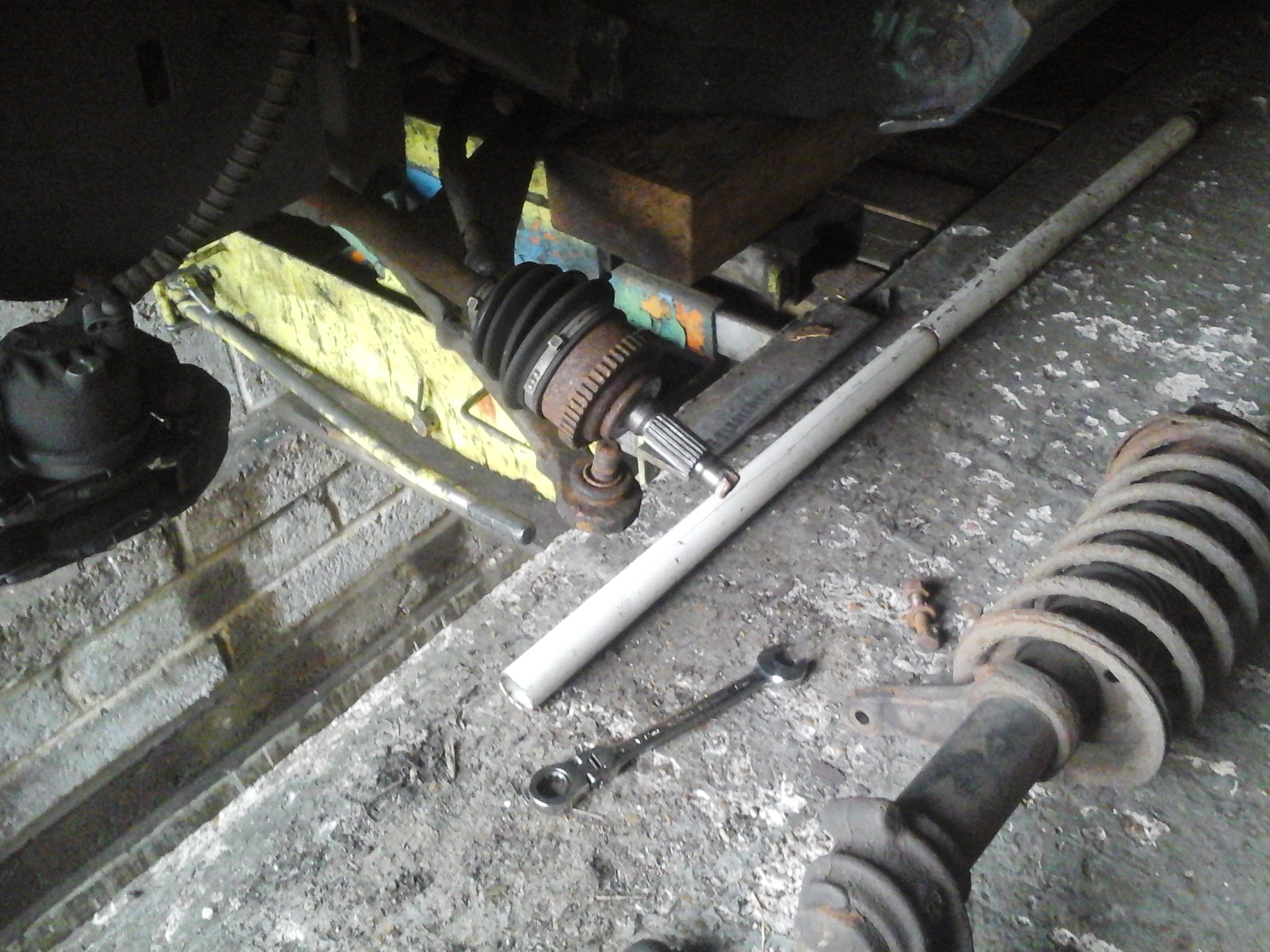
6.  Undo the two nuts holding the top of the strut. As you undo the last one use one hand to hold the strut up – if you don’t it will drop on the floor, the drive shaft will slide out of the final drive and oil will go everywhere!

2015-03-14 16.34.45

7. Lastly, tap the end of the drive shaft so it slides out of the hub. As you pull the strut away from the car ensure the drive shaft stays pushed fully into the gearbox/final drive to prevent any oil coming out. When the strut is free lay it down and carefully rest the end of the drive shaft on the wishbone. Hopefully it will stay there and no oil will escape.

2015-03-14 16.36.10

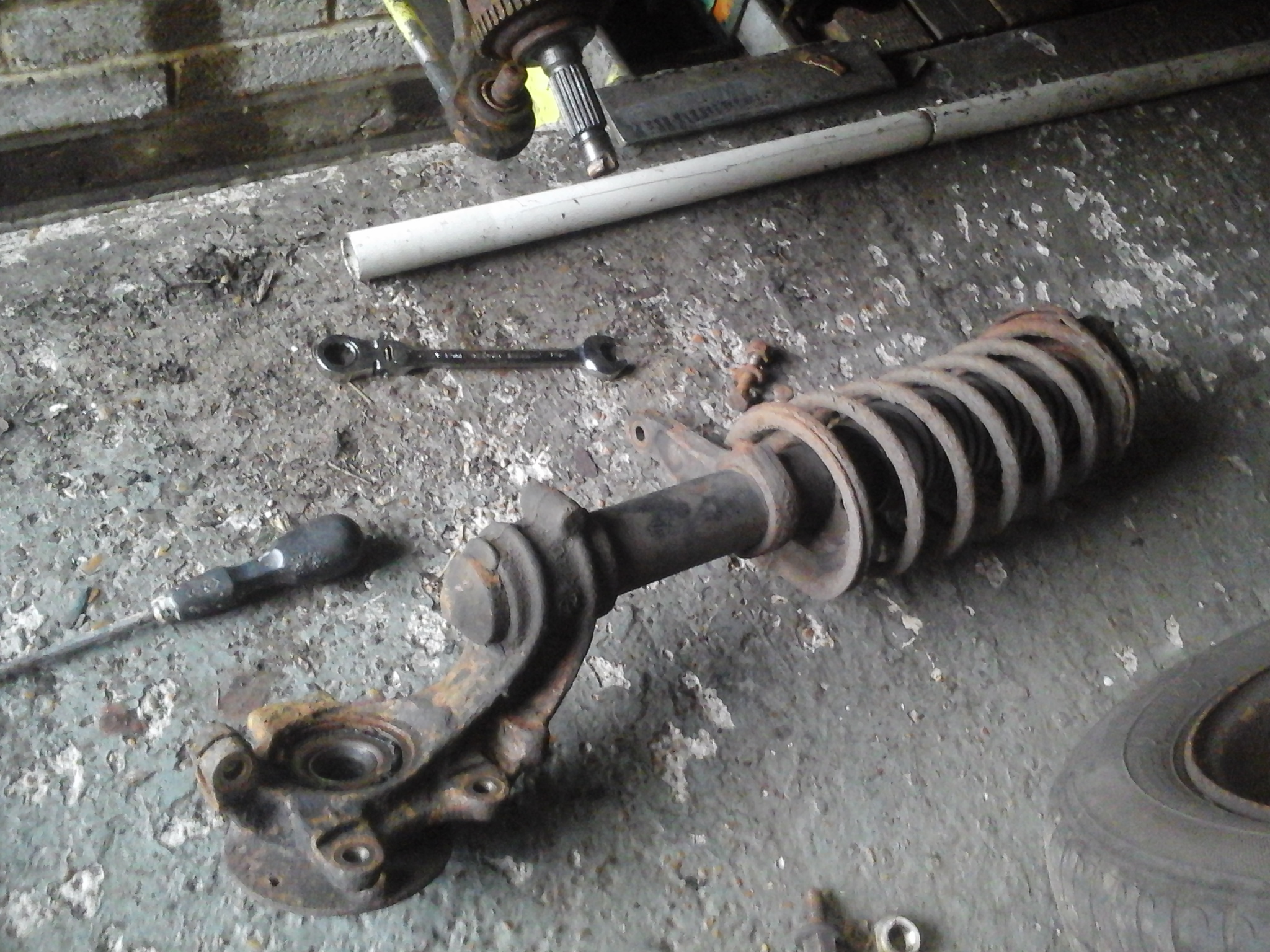
8. The strut is now free and the bearing can be replaced.

2015-03-14 16.36.15

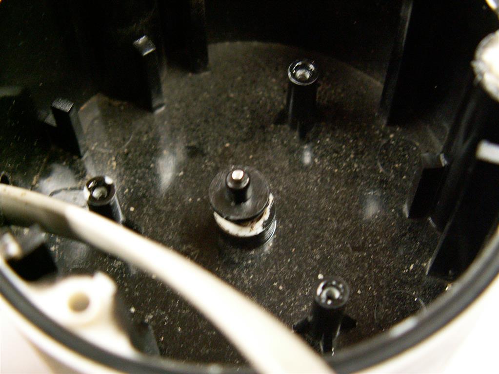
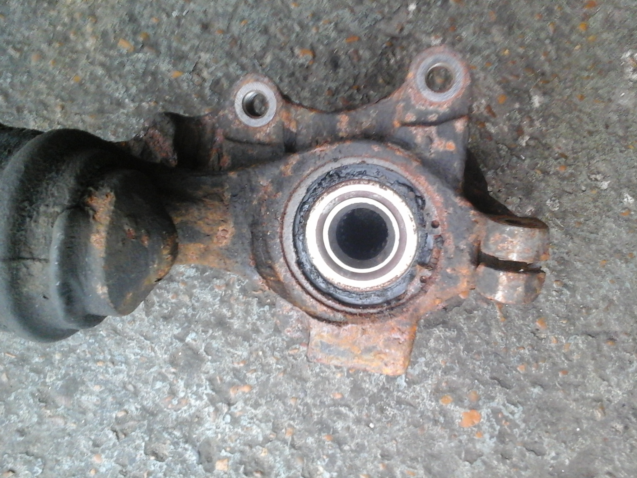
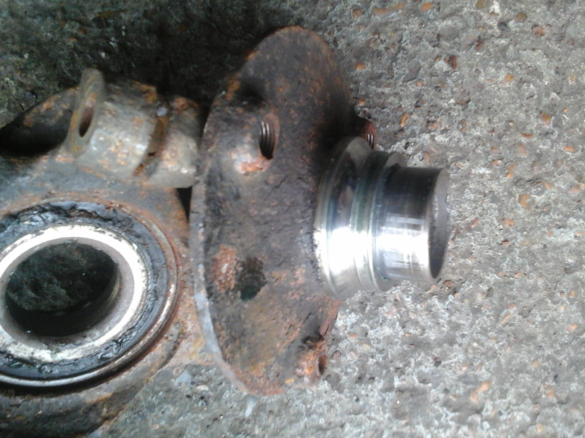
9. This pic shows the back of the bearing and the grease that has escaped – could this be the cause of the noise?

2015-03-14 16.36.47

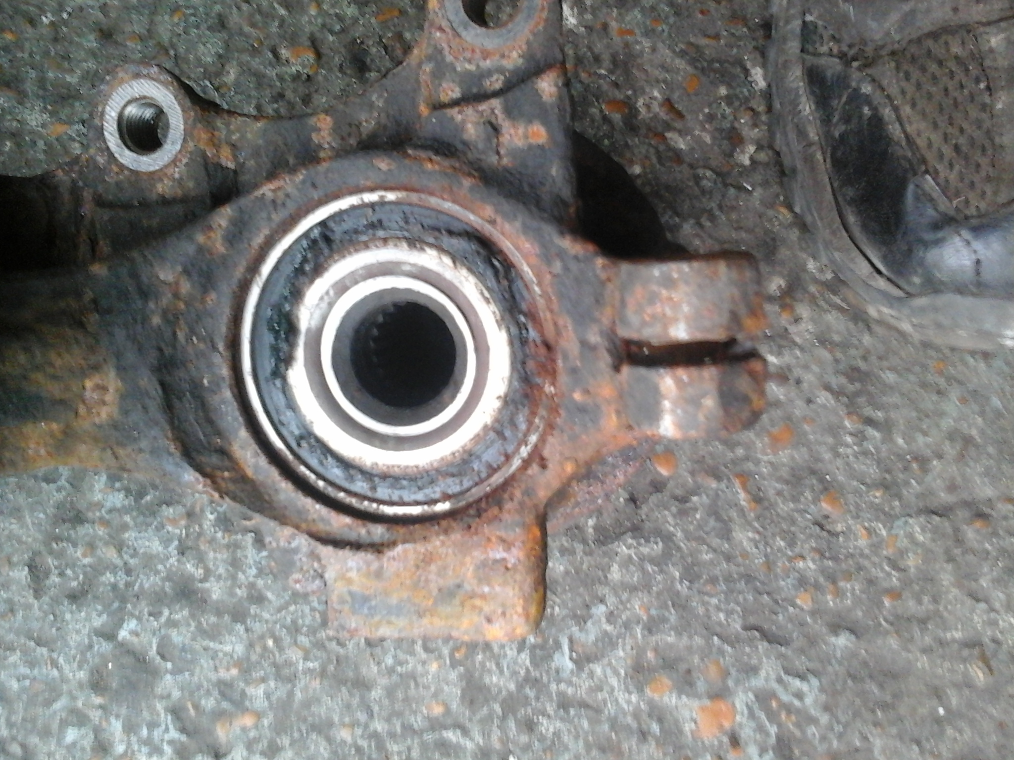
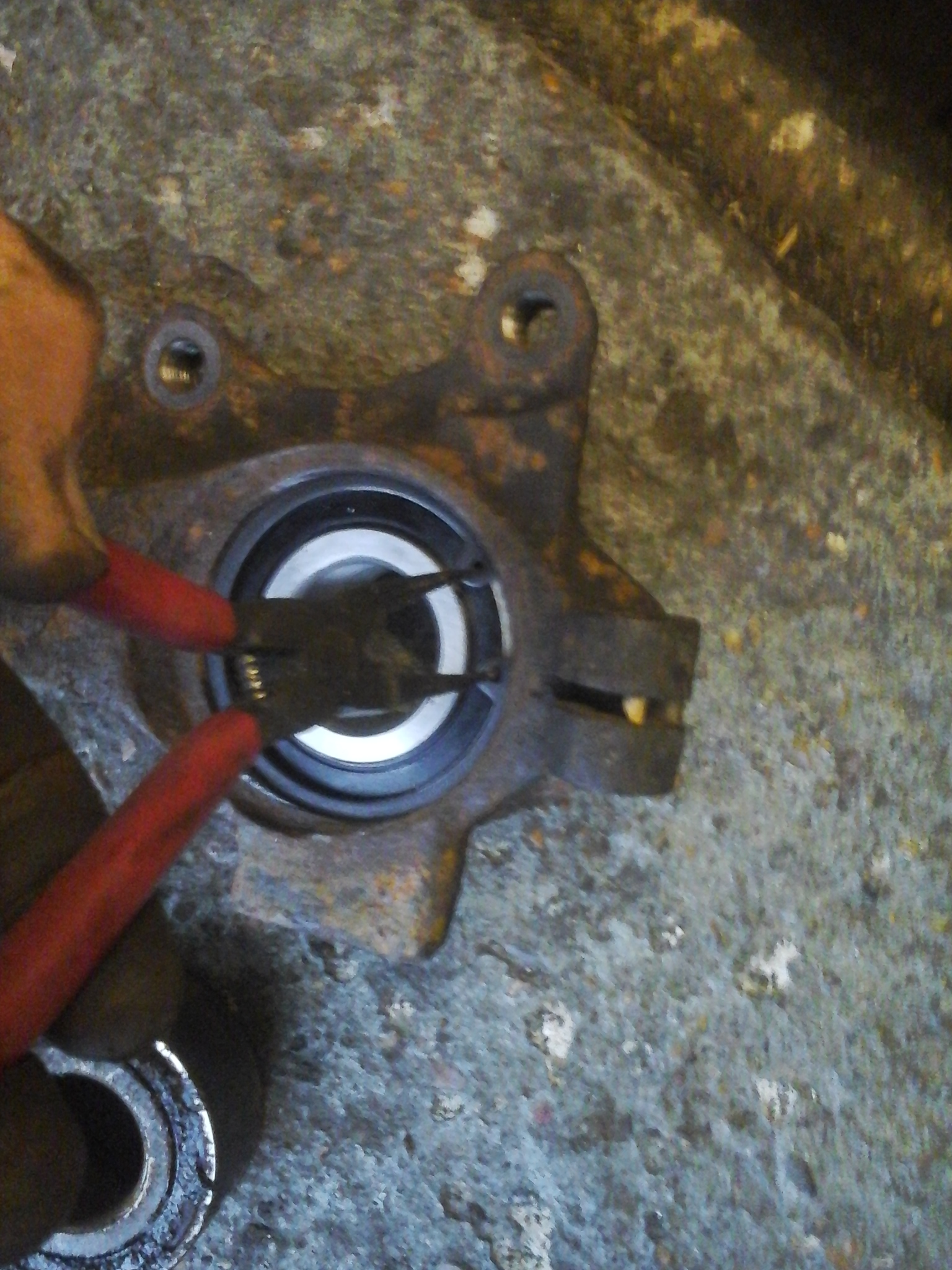
10. Now remove the large circlip, you may need to clean it up first using a wire brush and then free it off by tapping the holes in the end of the circlip with a punch.

2015-03-14 16.37.58

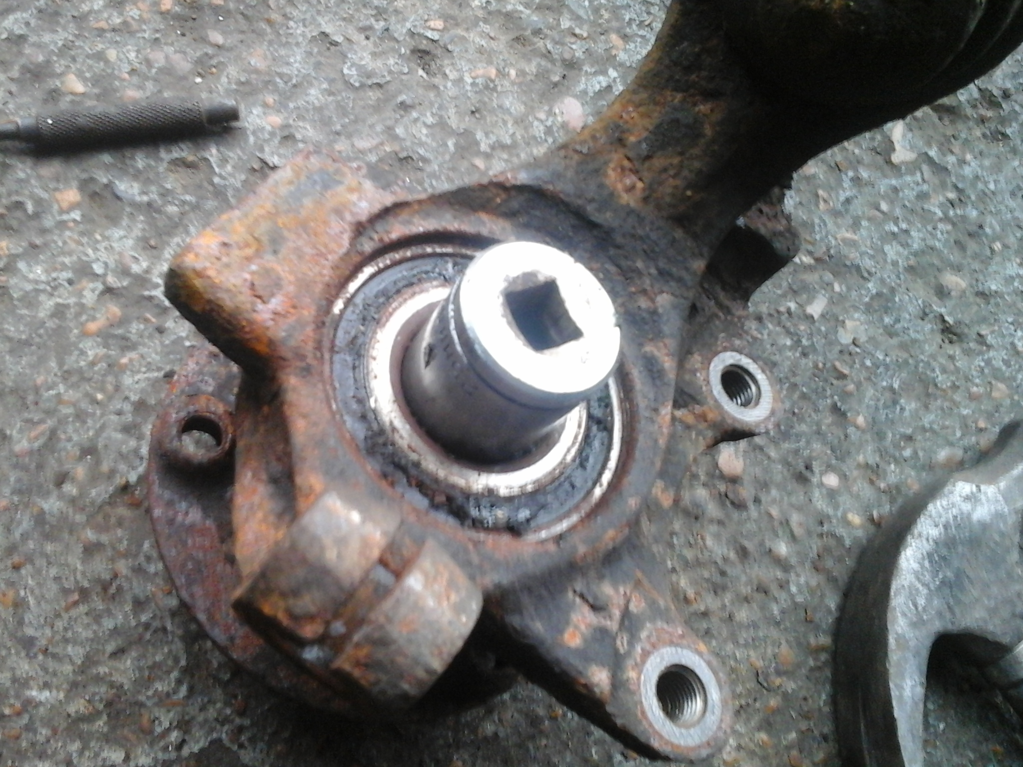
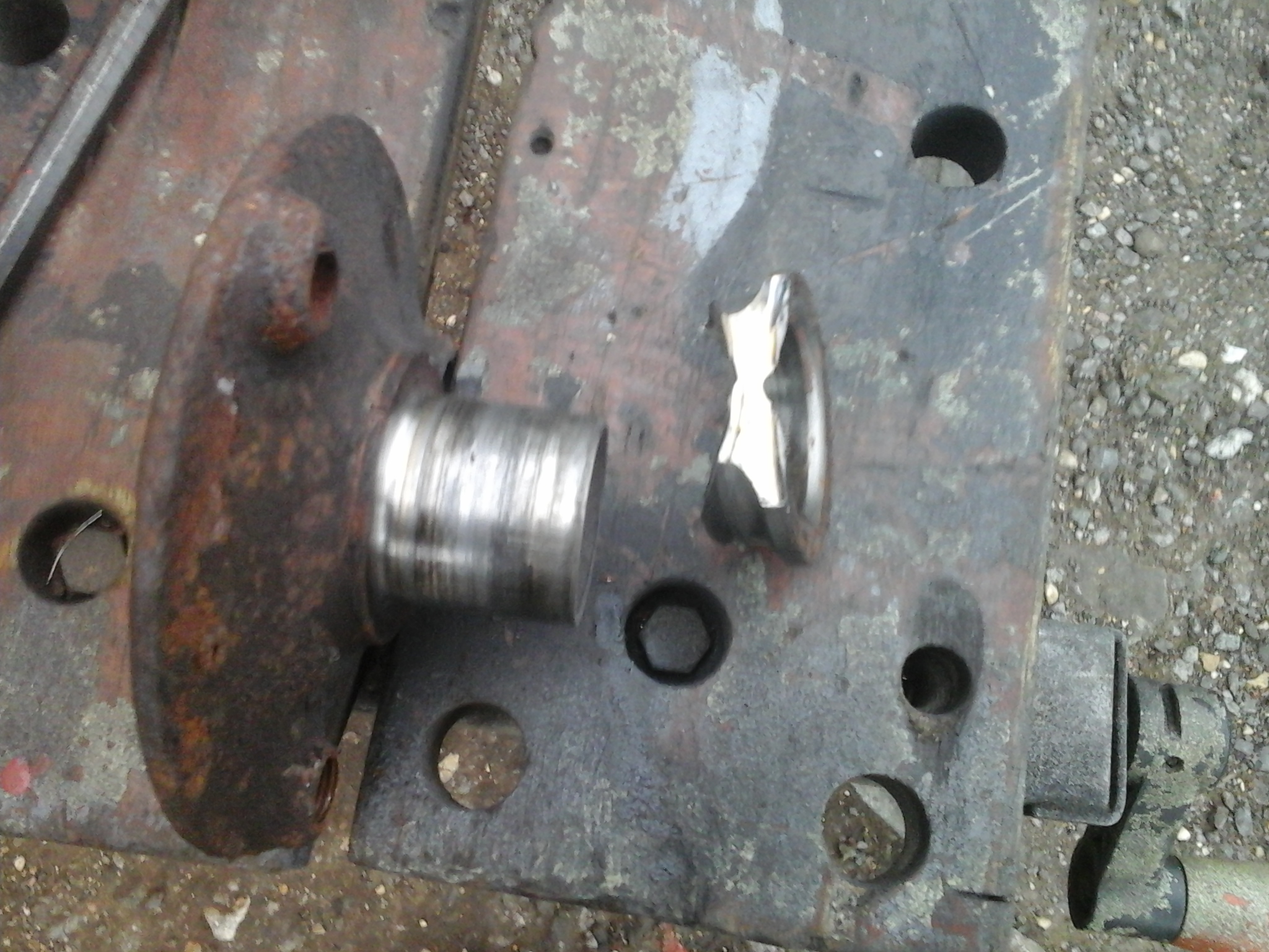
11. Now you need to separate the hub from the strut. Use a suitably sized socket to fit over the centre part of the bearing and hit with a large hammer. The hub will gradually come out, usually bring one half of the bearing inner with it.

2015-03-14 16.40.17

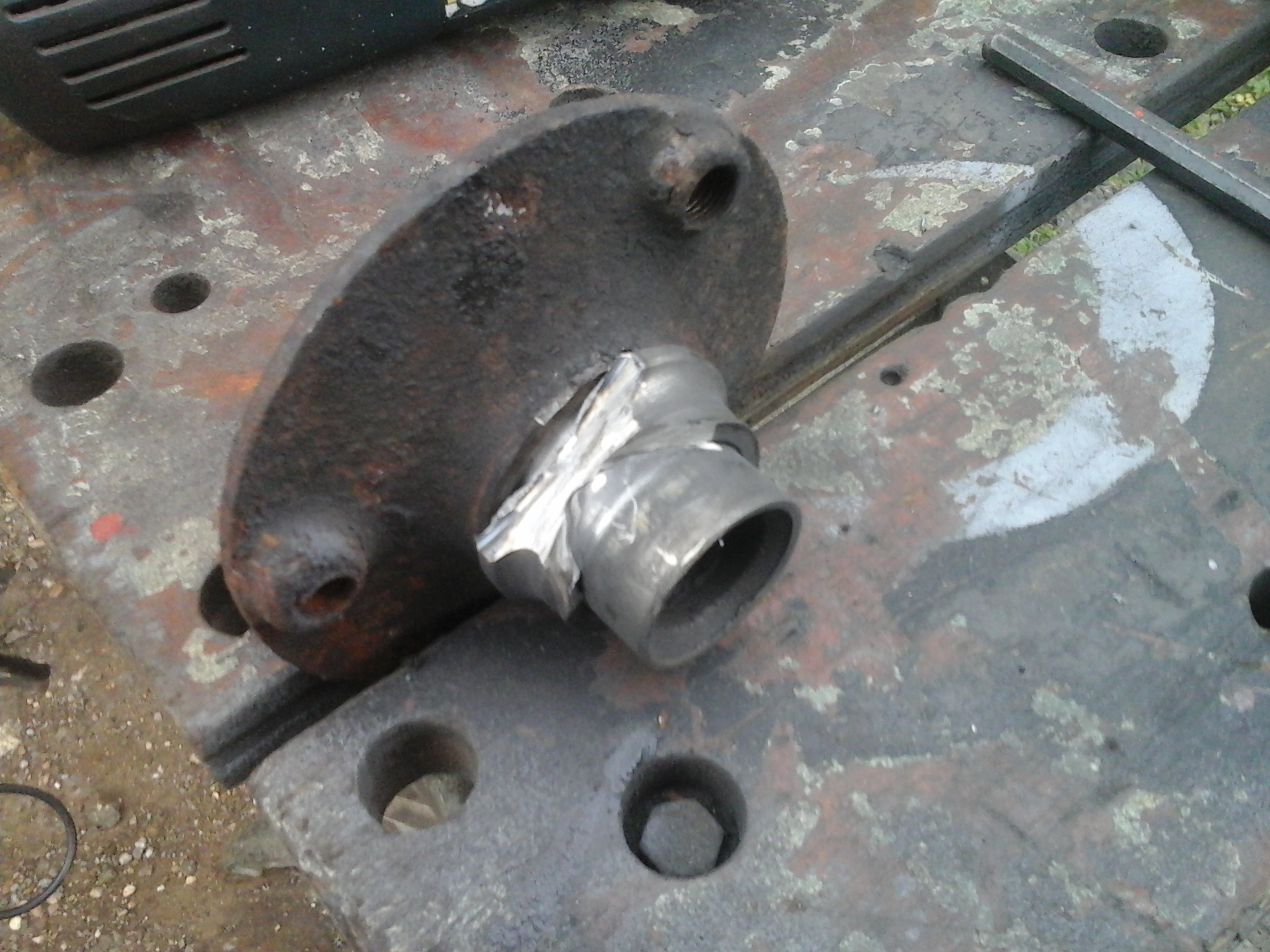
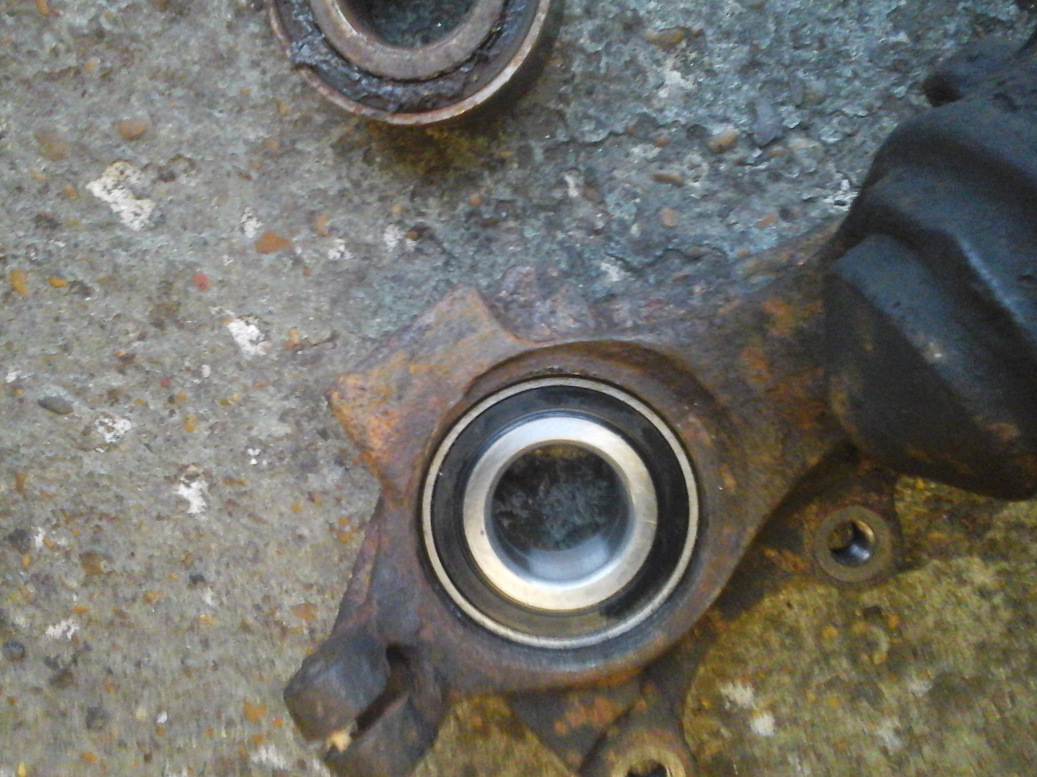
12. This pic shows the hub with the bearing race half still in place. You can waste time here trying to use bearing puller to remove it but almost invariably you will be wasting your time. The method I use is to cut it of using a small grinder fitted with a cutting disc.

2015-03-14 16.40.57

13. Take lots of small cuts and take care not to damage the hub. The bearing race is hard and the last bit will crack if hit with a small cold chisel.

2015-03-14 16.57.14


2015-03-14 16.57.19


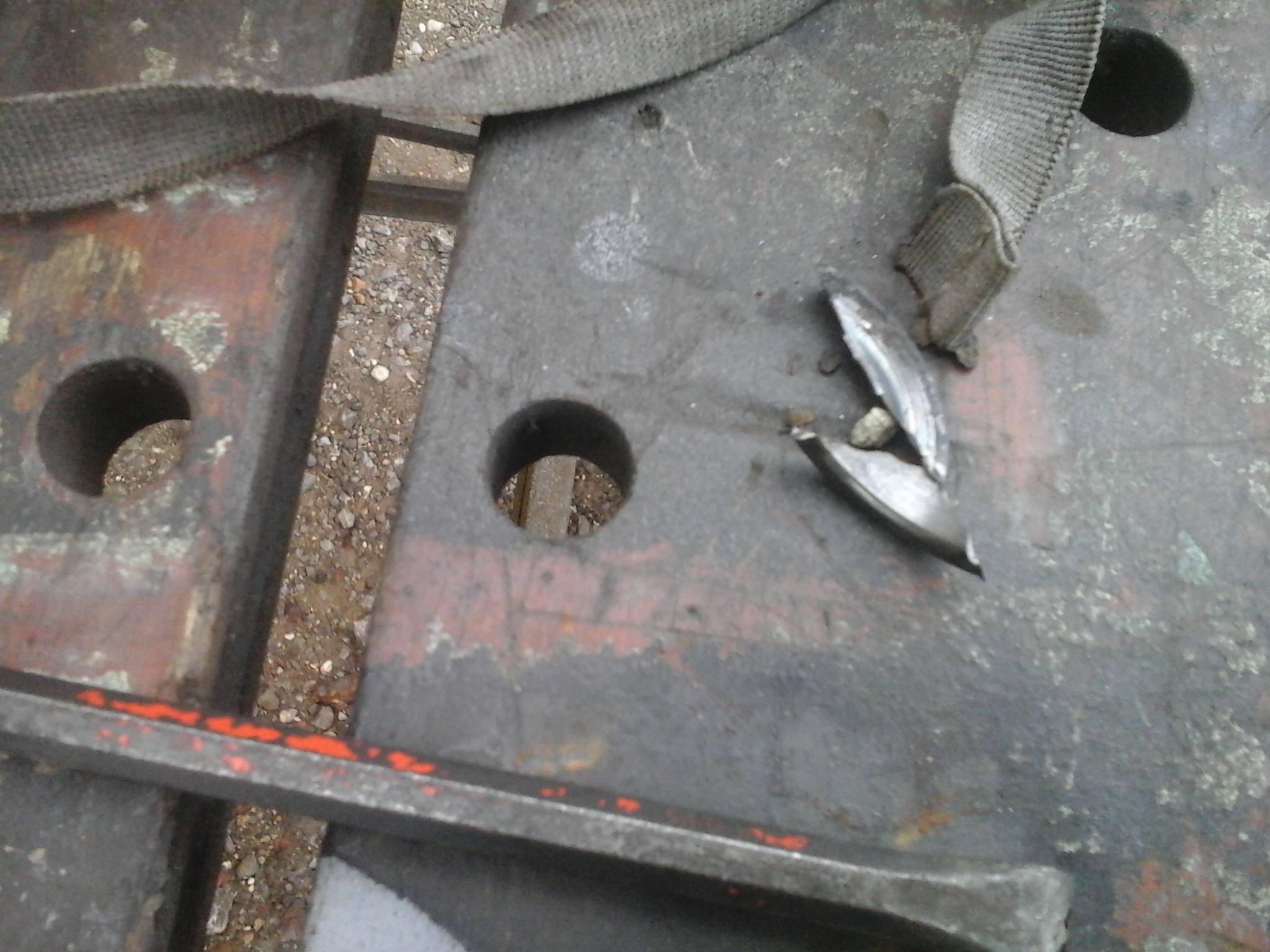
14. The inner race is now off. That’s probably the worst bit!


2015-03-14 16.58.33


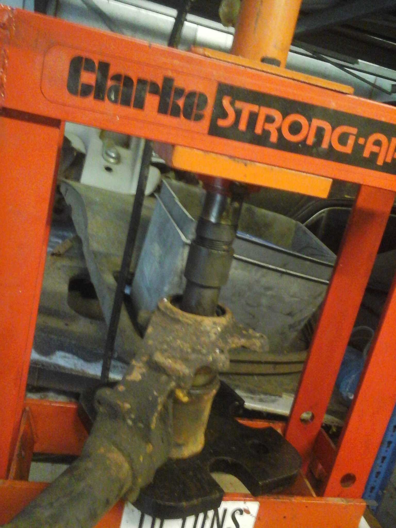
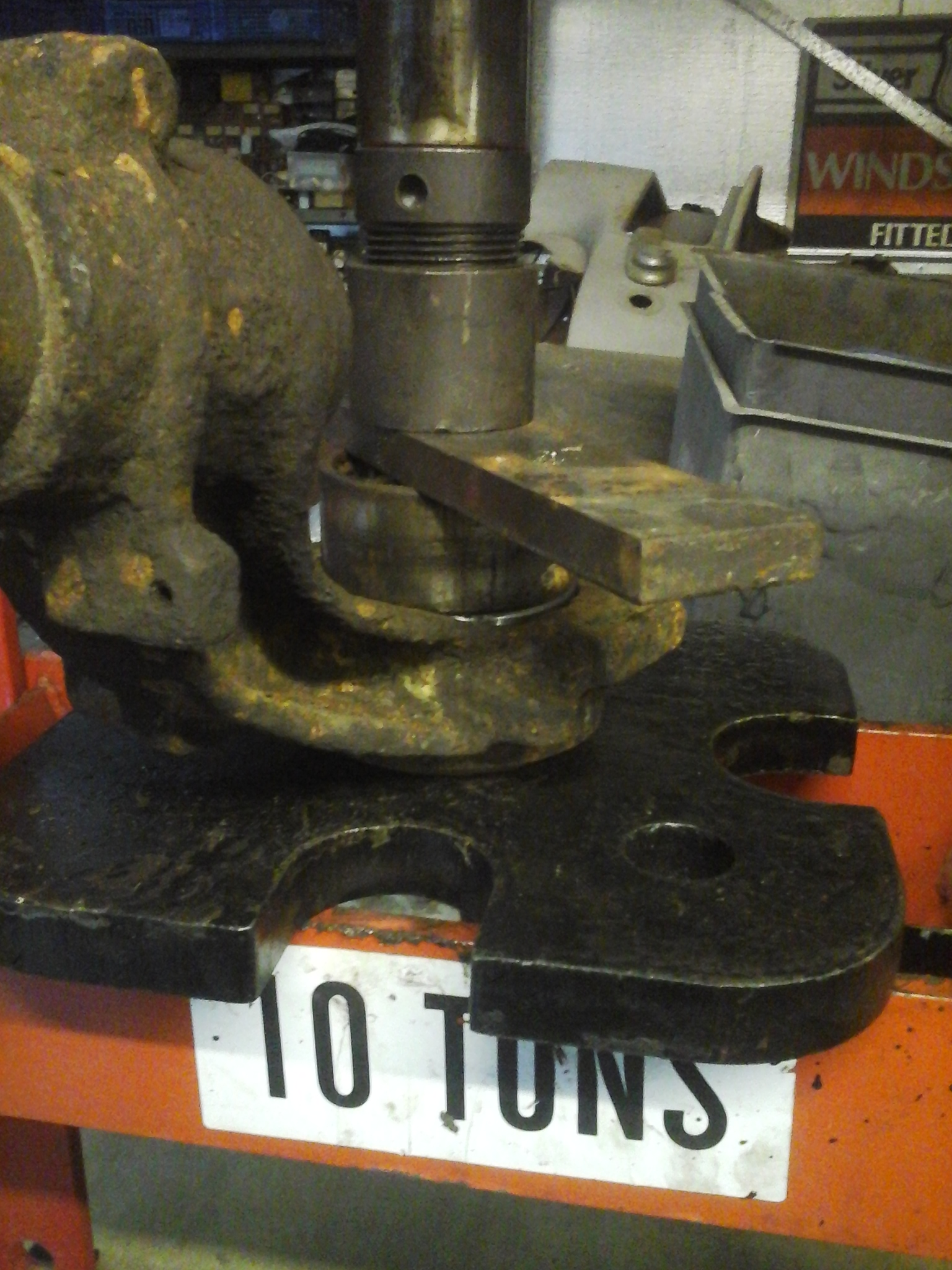
15. Now You need a press, support the under side on a large diameter tube – I use an old TU5 1.1 cylinder liner! Then press the bearing out, it will only go a little way but the press will crack the joint and get it moving. To finish the job off, remove from the press, rest the strut on a block of wood, use a large socket or similar and a large hammer and bash the bearing out It will move quite easily once the press has started it off.


2015-03-14 17.05.30

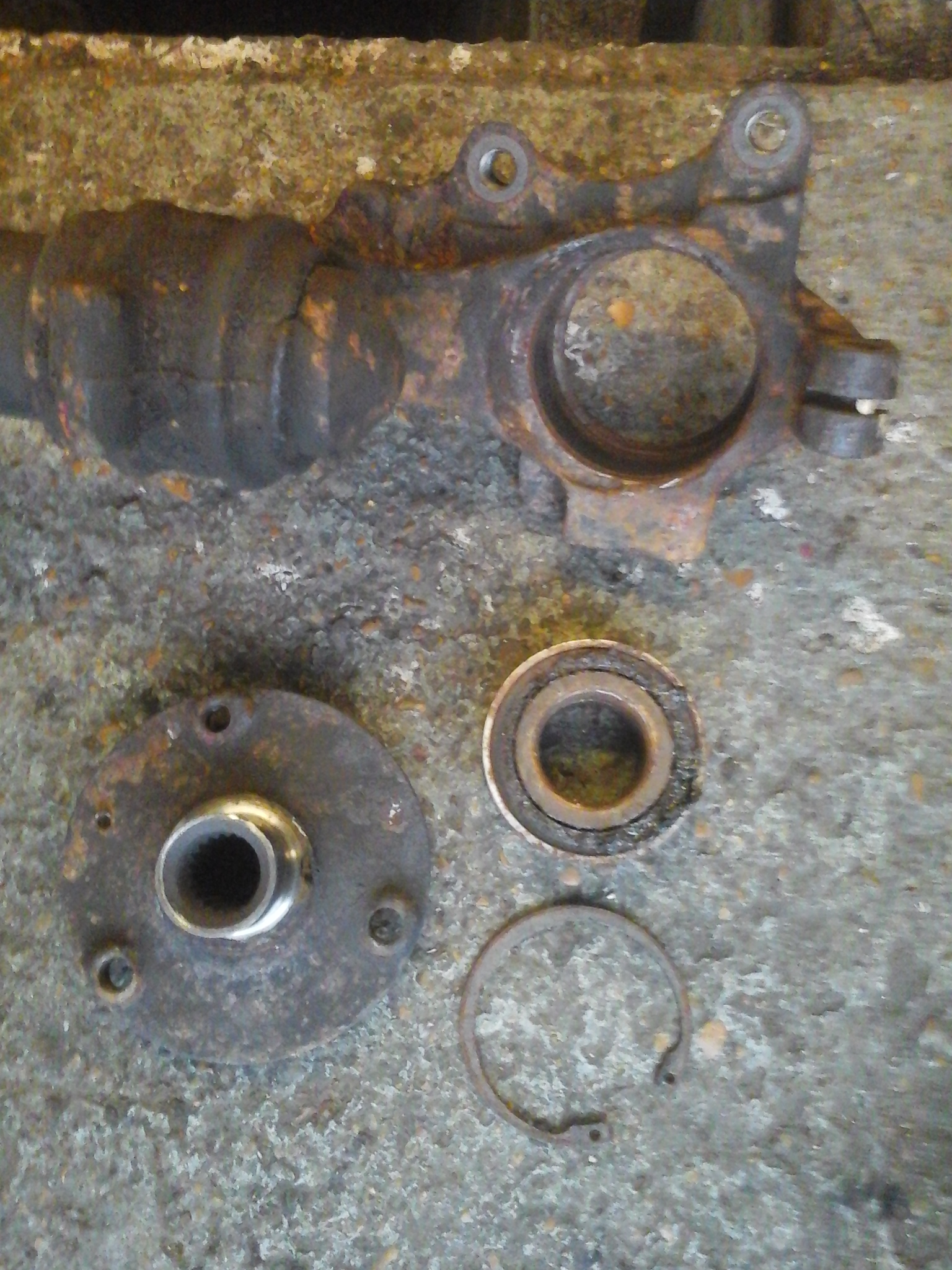
16. Here it all is in bits, justr wants cleaning up and putting back together.


2015-03-14 17.15.53


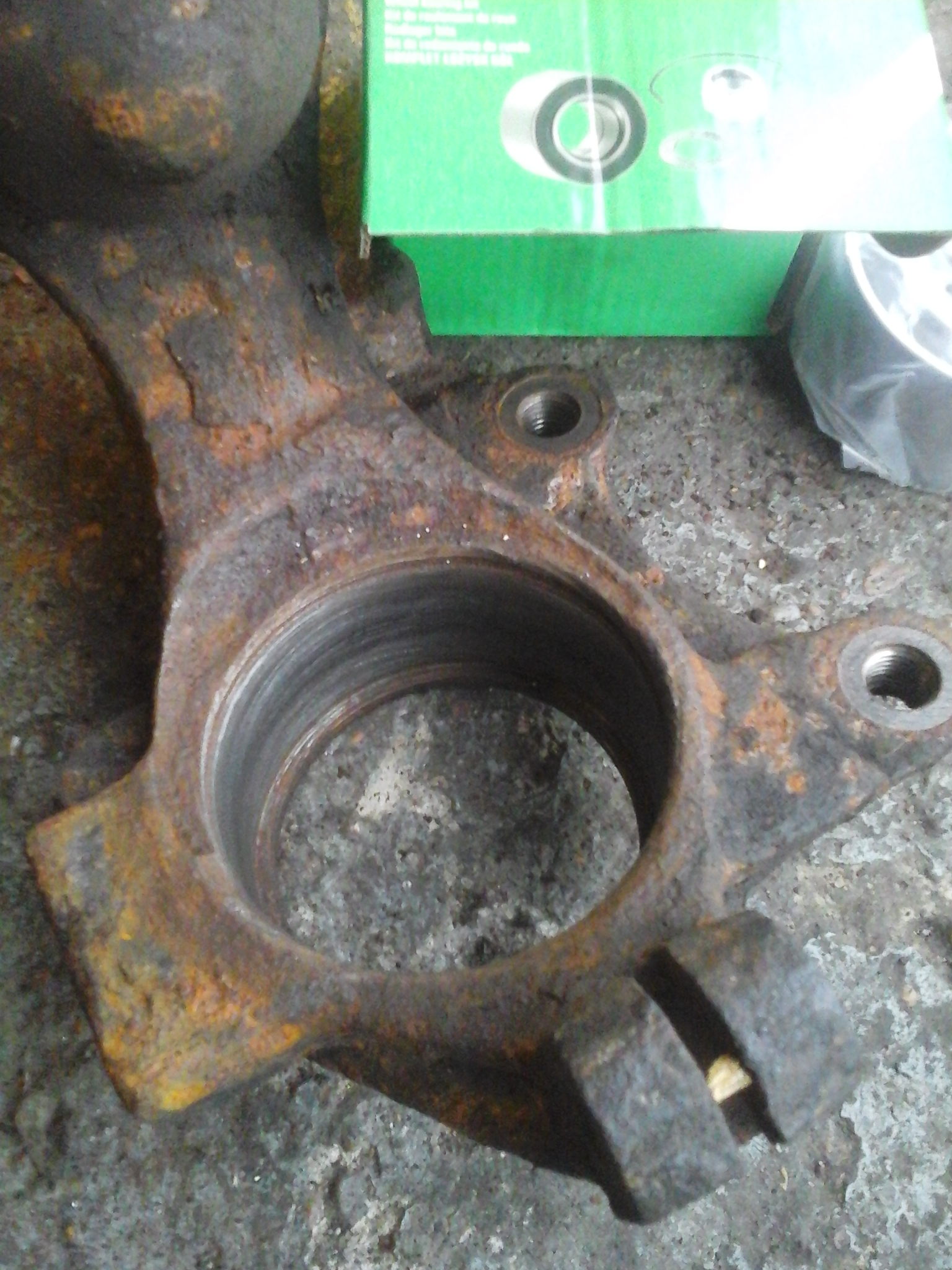
17. Clean up the recess in the end of the strut, ensure there is no rust or dirt around the bottom that will stop the new nearing going fully home, also make sure the groove for the circlip is clean.

2015-03-14 17.18.45

18. Next get the new bearing and smear the outside with a bit of oil to help it slide into the strut. Then go back to the press, ensure the strut is resting “square”, place the bearing in position, uses a thick metal bar to spread the pressure across the face of the bearing. Then press the bearing in.

2015-03-14 17.23.36

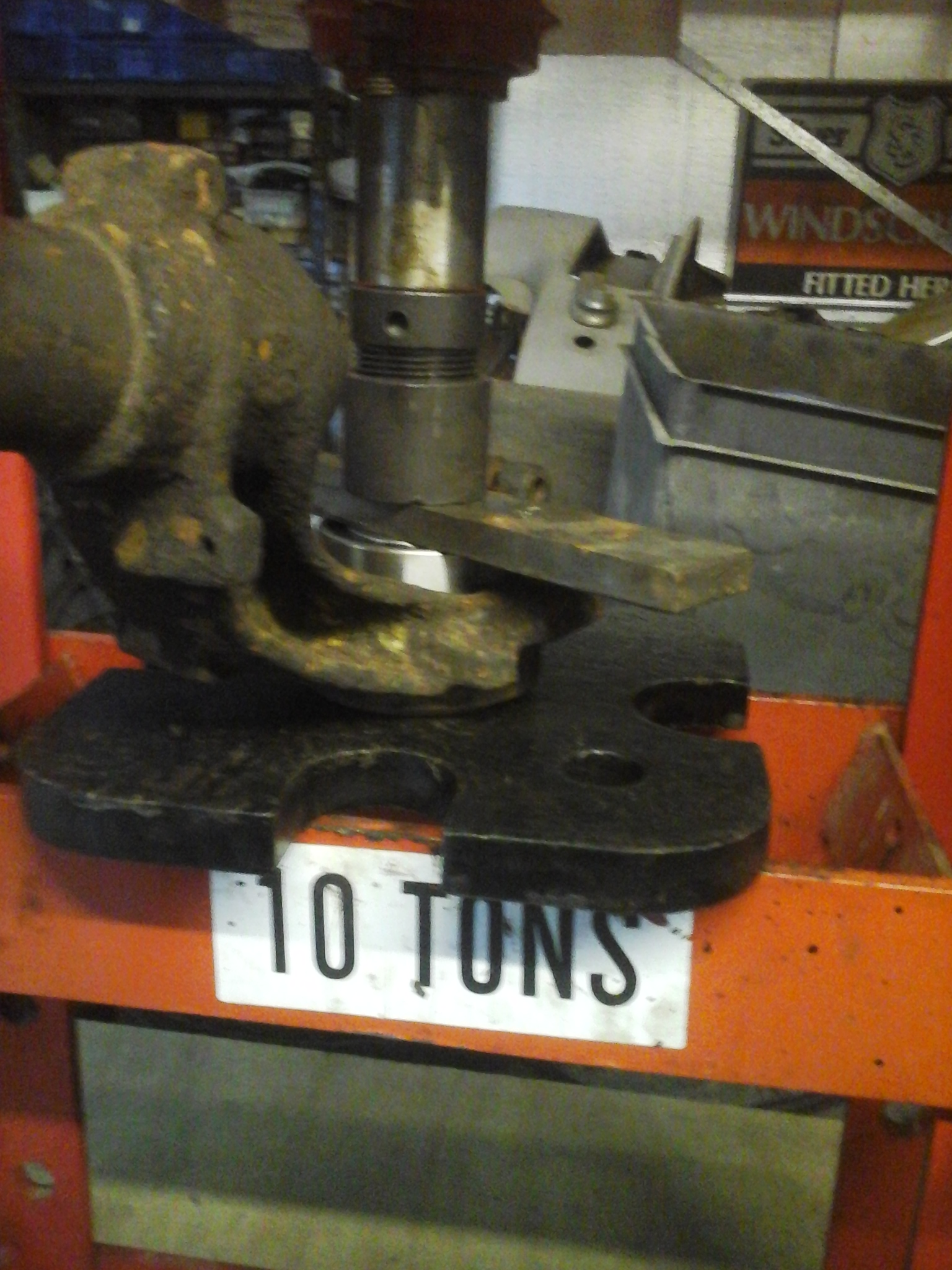
19. You need to use the old bearing placed on top of the new one to push the bearing fully home.

2015-03-14 17.25.01

20. Bearing is now in place.

2015-03-14 17.26.21

21. Now refit the circlip, ensure the circlip is fully seated in the groove.

2015-03-14 17.27.06


22. Clean the surface of the hub and cover with some oil and offer up to the strut. Squeeze the hub home in a large vice. Support the rear inner race with a large socket other wise the hub will push it out of the bearing. Finally refit the strut – in true Haynes manual style refitting is reverse of removal. Ensure all nuts are torqued up to manufacturers setting, Use a new hubnut and lock it, also use a new nyloc nut on the wishbone pinch bolt and track rod end. Also use some thread lock on the two calipper bolts.

2015-03-14 17.41.50


23. Finally go for a test drive. If you are fortunate you will find the noise has gone and the car is almost silent apart from the clatter and growl of the diesel engine. In my case it was still noisy. So time to look at the drivers side. Exactly the same procedure. This time however the bearing was really rusty and felt really rough. Once replaced the car was indeed it’s usual refined self!

Citroen AX 1.5D

This section of the mountain may (or may not) cover the “restoration” of a 1995 Citroen AX 1.5D, purchased by my youngest son for not a lot of money as a replacement for his AX Dimension of the same age. “It’s quite good dad” he announced as he assured me he had checked all the usual areas for rust – inner wings at the front, front bumper mounts, “Y” chassis box section below the front seats and the rear end of the sills. More worrying is the horrific “grinding noise” clearly audible above the clatter of the 1.5 litre diesel engine at anything above 5 MPH !!!.

Anyway this weekend saw the start of me taking a closer inspection.

2015-03-14 15.23.40Started by stripping off headlamps, indicators, bumper, grille and bonnet. At this stage the extent of some of the rust could be seen.

2015-03-14 15.23.54Inner front wing, notorious rust spot Peugeot 106’s don’t rust half as badly here as the have full wheel arch liners, the AX only has liners for the rear half of the arch so this area suffers badly. If you are lucky you can pick up a scrap 106 and cut this section ou – its identical and makes a perfect repair panel.


2015-03-14 15.24.04


This is the passenger side inner wing. The previous owner as spread a bit of body filler in the affected area – pretty useless really.

2015-03-14 15.24.23This is sign that the rust is worse than first thought. Its the cross member below the radiator, though you can’t see it the rear seaction has rusted right through. The good thing is it is a simple square box section so easy to fabricate and graft in a new one!

2015-03-14 15.57.51

Front wings removed.

2015-03-14 15.58.05

This reveals the rusty bumper mounts and rust further up on the inner wing. (below)

2015-03-14 15.58.50

Drivers side bumper mount – really quite weak. (Not that the AX was ever strong even when new)

2015-03-14 15.59.13

Disappointingly the wings themselves which ar e usually very good were rusty around the edges – may try to get hold of some better ones.

2015-03-14 15.59.22


Having depressed myself with the amount of rust repairs I thought it best to move onto checking out the grinding noise.  This to me sounded like a really shot wheelbearing – especially as it disappeared when cornering left and got worse when cornering right. I guessed nearside (passenger side to the layman) – see next post for wheel bearing replacement.


More Rotten Apples.

So this week Apple announce yet more massive profits to add to their already huge cash pile. Last quarter they sold 34,000 iPhones an hour, every hour, 24 hours a day, seven days a week. Well done, it’s obviously a great product that people want. They charge a premium price, make a nice margin, in excess of 30% so we are told. So imagine how much I wanted to share the love with the great people at Apple when today I need to purchase a few sample Apple Authentication Chips for a project, a project where a product will be made that works with Apple devices. The chips are a quite reasonable $1 each, but when you go to the check out -[  bear in mind there is one single Apple approved supplier for these thing in the whole world – and you have to jump through hoops to be able to purchase from them ] – you suddenly get hit with a $50 SERVICE CHARGE – for what??? Then the final icing on the cake is when you select the delivery option – for 20 “chips” each only a couple of mm square – you get hit with a carriage charge of $70 – so $20 for some sample chips weighing a couple of grams and a grand total of $120 (one hundred and twenty dollars US) for postage and packing!  That really takes the biscuit – especially as their evil twin Amazon will only yet your average punter charge £2.80 for carriage on any books you try to sell on Amazon – even if it costs more because its a big, heavy book!

People have a go at Microsoft saying they are evil but at least Microsoft now have the decency to give all Windows 7, 8 & 8.1 users the chance to upgrade (if that’s the right term!) to Windows 10 when it is released. Also don’t forget that Bill and Melinda Gates are actually giving away the $Billions that Bill made from Microsoft doing some real good in the world.

It’s about time our wonderful E.U. and the U.S. got together and started taking Apple down a peg or two from their pedestal instead of creating endless red tape for little companies.

The Royal Institution Christmas Lectures – 2014 – Sparks Will Fly.

I have been a fan of The Royal Institution Christmas Lectures for many years. Admittedly I have not watched so many in recent years but I always thought fondly of them. This year I made a concerted effort to watch them – after the event, and after Christmas via the mystical magic of t’interweb and BBC” eye” player. The titles and write ups seemed quite exciting and up my street, making stuff by using “technology” we have around the house. The presenter, Prof Danielle George is Associate Dean for Teaching and Learning in the Faculty of Engineering and Physical Sciences, and a Professor in the Microwave and Communications Systems research group at the University of Manchester. She was bright, enthusiastic and engaging and I accept the target audience was a lot younger than me – though I am sometimes told I am just a big kid – so she needed to engage their imagination but pretty much from the off important facts and principles were glossed over, things were dumbed down, my expectations were raised way too high. We jumped from using an incandescent lamp to LED lamps for reasons of energy efficiency, no mention was made of the thermal lag of the filament making for blurry images. Then we got onto matrix displays, there was quite a good piece of demonstration equipment but it was not well explained, words like multiplex and matrix (I think) were sadly missing as was a very important phenomenon – persistence of vision – which allows us to get away with all sorts of tricks with visual displays. Things got worse when we had 40 Raspberry Pi’s apparently triggered in perfect synchronisation “by the internet”. No mention of latency and timing.  We were led to believe that wireless was better than cabling in a large building, we had a demonstration of a mechanical SERVO not a simple motor switching a light on and off, then magically someone pops off down B&Q and buys their entire stock of multicolour, wireless enabled LED lamps. Plug them in, throw in a ready made wireless controller from a stadium illumination and a game controller which had nothing to do with a load of Jellies! and the jobs a good one!

The second lecture was no better, in fact it was worse as in my opinion it had the biggest bit of misinformation of the three. What they showed in the studio was not a Hologram, it was a 2D image projected onto a curtain of water droplets, quite effective but NOT a hologram. There was a whole section on Haptics (not clearly explained) and then the final implementation didn’t use them – they could have done.

The third lecture bought in a load of ready made bits and robots to form an orchestra. All very interesting but little was explained about many of the things used, there were a few nice demonstrations but the fundamental science was glossed over.

I know it is difficult to get many of the concepts over in a one hour program but I often got the feeling that Prof.  George was out of her depth, there were so many things I could pick holes in (Sorry Prof. but it’s true). I also felt there were hidden agendas throughout – energy efficiency (LED lamps), high speed wireless internet There was also an over reliance on the Smartphone with little in the way of explaination of the basic principles.

The one good thing was the over arching message to the audience to go home and play, to make and do stuff. My only worry is that many will become quickly disillusioned when much of what they imagine they can do – like “code” a game (how I hate that term – almost as much as hack), and they suddenly find out its not a case of a couple of lines of program but many hundreds.

Raspberry Pi, Arduino and their ilk are fantastic and have fired many youngsters imaginations. Hopefully in 10 years time we will start to see the fruits of this emerging into main stream employment, I hope so as we are so short of engineers of all flavours right now. I think the program should have concentrated on this and showed right from the start of unpacking the kit what could be achieved from getting “Hello World” on a screen and blinking an LED to uploading a web page to the internet. Telling them how it all links together – its information no one thinks they need to know – but in the long run they do!

Weather Station Repairs – Technoline WS2350

If you click on the tab at the top left hand side of the home page you get taken to the “Weather” page where there is a link to my other website displaying current weather data at Dengemarsh. The “system” for collecting the data – Windspeed, direction, pressure, temperature, humidity, ranfall etc. is a Technoline WS2350. This is similar to the La Crosse WS2310.

I first set the system up in 2007. The Weather vane and anemometer sits on top of a 9m mast – well clear of the turbulent effects of nearby buildings. The website is very popular with the wind and kite surfers who frequent the nearby beaches at Greatsone and Camber. They like it apparently as it gives very accurate windspeed and direction information – important so I am told for maximum enjoyment of the sport! It is also heavily accessed by fishermen who fish off of Denge beach and Dungeness Point.  I must point out at this point that I don’t enjoy or indulge in any of the above activities!

The original anemometer had a small propeller underneath attached to the weather vane which kept it facing into the wind. This lasted about 12 months and was replaced by the more traditional and more accurate “three cups” design. The first one of these lasted around 3 years before I noticed the wind direction “sticking” and the windspeed grossly under reading. Having taken the mast down I quickly ascertained that the “bearings” were worn and decided to get a new LAC TX-20 Windspeed and Direction Sensor. This was duly fitted and lasted a similar time to the first – we are near the coast its windy most of the time, the wind is also salt laden when from the southwest so the short life is not overly surprising on a relatively low cost system (The whole station currently retails at £110). So this time I decided to strip the unit down and see if it could be repaired, Also the sensor were showing out of stock every where I looked.

Step 1.  Remove the sensor from the mast – lower the mast, undo the U clamp holding the sensor to the mast and disconnect the cable, then escape to the warmth of indoors!

Step 2.  Remove the 3 screws seen from the underneath.

2015-01-18 20.41.19 (Medium)

Step 3. carefully separate the direction indicator top half from the anemometer bottom half.

KONICA MINOLTA DIGITAL CAMERA

There is a small, square LED that is a snug fit into a plastic lightguide, It does just slide out  Just “wiggle” the top and bottom halves gently separating them and it will come out.

Step 4. Gently lever out the PCB, be careful as there are two thin black wires attached to the underside of the PCB that connect to the magnetic sensor that detects the windspeed.

KONICA MINOLTA DIGITAL CAMERA

Step 5. Finally you will be able to see a black plastic base plate, the one in the picture has the wires disconnected. Remove the three screws and carefully lever the base plate out, you can gently lift on the legs of the magnetic sensor, hold the data cable out of the way.

KONICA MINOLTA DIGITAL CAMERA

Step 6. You can now see the top bearing of the anemometer. The bearings are really small roller bearings. Lift off the bearing from the spindle.

KONICA MINOLTA DIGITAL CAMERA

Step 7. Next CAREFULLY ease the small round magnet off of the plastic carrier. The magnet is quite soft and will break easily.

KONICA MINOLTA DIGITAL CAMERA

Step 8. Now using the blunt end of a screw driver (i.e the handle) carefully push down on the exposed spindle end whilst supporting the casing. The spindle is a push fit through the lower bearing and the plastic magnet carrier. Once the spindle has started to move you should be able to ease the plastic carrier upwards and remove it from the spindle. The spindle should then be easy to pull out from the lower bearing. Once removed tip the housing upside down to let the lower bearing drop out. You will be left with 5 components, Cups and spindle, lower bearing, plastic magnet carrier, magnet, upper bearing.

KONICA MINOLTA DIGITAL CAMERA

Ok that’s everything dismantled. Now when you examine the parts you will probably be ably to see the wear on the bearing cup for the wind direction sensor. The picture below shows the wear I found, it was the same on both units is dismantled.

KONICA MINOLTA DIGITAL CAMERA

There are various options for repair. I chose to remove the remaining “wall” with a knife and using my 3D printer make a small stepped washer to fit over the brass bearing.  (See my 3D printer post to see what I am talking about!). The whole process of making two washers, one for each of my sensor units, took about 25 mins, that was measuring, drawing the 3d model, and printing two repair pieces.

washer screenshot (Medium)2015-01-17 14.48.06 (Medium)

The stepped washer was a good fit and snapped over the remaining stub needing no glue – quite satisfying! It can’t come off as the spindle from the vane will keep it in place.

KONICA MINOLTA DIGITAL CAMERA

Rest of wall removed

KONICA MINOLTA DIGITAL CAMERA

Stepped washer in position

Now onto the anemometer. The problem here seemed to be the excessive play around the roller bearings. This  allows the spindle excessive sideways movement leading to the hub of the plastic cups rubbing on the body of the unit. This obviously causes a lot of drag affecting the wind speed readings. It appears that the bearing outers were free to rotate in the plastic recesses designed to locate them. Over time these have worn. I took the easy way out and used the hot tip of my soldering iron to melt the inside of the recess causing lots of little ribs. I the pressed the bearings back into the plastic with the iron. Care is need to ensure the bearings are centred within the moulding. This done it was simply a matter of reassembly.

KONICA MINOLTA DIGITAL CAMERA

Ready for reassembly. (black wires soldered back onto the sensor)

It does not matter which way round the black wires go. Check both ends before you put it back together, the wire is very thin and easy to break, better to remake the joints at both ends and be sure they are OK than put it all together and find out one has broken on reassembly.

To reassemble first slide the spindle of the cups through the lower bearing – which should be securely held in the moulding.

KONICA MINOLTA DIGITAL CAMERA

Next carefully press on the plastic magnet carrier, make sure you get it the right way up. Press it on so that the spindle just pokes through. At this stage I put a couple of drops of very light sewing machine oil on the each of the bearings – I suppose you could use WD40 if you are a fan (bear in mind WD40 is a water dispersant  hence the initials WD and NOT a permanent lubricant).

KONICA MINOLTA DIGITAL CAMERA

The place the magnet over the carrier.

KONICA MINOLTA DIGITAL CAMERA

The place the base plate into the moulding, make sure you get it round the right way and make sure it is full seated on the three pillars. Whilst holding it all together squeeze the cups up wards so as to push the spindle through into the upper bearing. You want to make sure it is pushed up sufficiently to remove most of the play but not too much so that it rubs on the moulding. Check it is free to rotate. If all is well fit the three screws. If not pull it apart again and find out why not. The crucial thing is to make sure both bearings are secure and do not have any free play in the housing which causes side ways movement of the spindle allowing the cups to rub.

Next put the PCB in place, again watch the orientation.

KONICA MINOLTA DIGITAL CAMERA

Now you can fit the top part – first check the rubber O ring seal is still in place around the edge of the lower part. Make sure you guide the LED into the slot in the light guide in the upper part. Also make sure the top part is correctly aligned – East should face away from the mounting arm – there is a little raised pip to align on the upper and lower mouldings as shown below.

KONICA MINOLTA DIGITAL CAMERA

Finally refit the last three screws to hold the whole lot together.

A quick check to make sure it all works before refitting to the mast and hopefully that is it for another couple of years.

Weather website is here if you are interested:

www.thejonesgroup.co.uk

I’ll add more info on the station later – such as how to fix the rain gauge, and how to add an external aerial to improve wireless range.

Rotten Apple

Make no mistake, Apple make lovely products, they look good, feel good and generally work well. Superbly thought out and developed user interfaces etc. etc. BUT ………….

Ethical ? Not in my opinion.

Fair? Not in my opinion.

Ruthless? Yes, in my opinion.

Controlling? Yes, to the extreme, in my opinion.

Unreasonable? Again yes, in my opinion.

Why? You may ask. Well I have spent (wasted) a large chunk of my day at work crawling through the fog of Apple’s MFi program trying to find a datasheet or even just simple connection details for their MFi Authentication chip. Sorry but can’t go into too many details as the boys from Apple will come round and beat me up, it says so in para 31415926.2 of the MFi licence agreement, the one way contract where Apple get all of our stuff but we still can’t get diddly squat from them. ( that was all of course a light hearted joke!).

Eventually I found an email contact, no search facility on the MFi Portal, and emailed them with my request. Got an auto response saying they will try to get back to me in 3 working days – ah well at least I have an excuse for 3 of the days late the project will be.

Forgot to say that whilst searching for the info I wanted I wasted another 30 minutes following Apples advice and signed up for the Developers section, yet more terms and conditions!, where apparently I would find more information. Well there is b$#@er all there to do with hardware, its all software development.

Rant over!

Royal Instition Christmas Lectures next…………

Nice Moonrise

Its 6th January 2015, noticed a lovely moonrise at about 6:00pm this evening. Not the worlds best photograper but you get the idea. (the pics at the top of this blog are either a) sunrise behind Dungeness Power Station, or b) sunset towards Fairlight

KONICA MINOLTA DIGITAL CAMERA KONICA MINOLTA DIGITAL CAMERA KONICA MINOLTA DIGITAL CAMERA KONICA MINOLTA DIGITAL CAMERA KONICA MINOLTA DIGITAL CAMERA KONICA MINOLTA DIGITAL CAMERA KONICA MINOLTA DIGITAL CAMERA KONICA MINOLTA DIGITAL CAMERA

The Lister Lives…….

I refitted the Lister to the saw bench today. Bolted it down, refitted the fan, flywheel and pulley. Then fabricated a longer exhaust pipe to  take the smoke well away. Next I made a shield between the engine and the bench to stop the saw dust being sucked into the fan, I simply used a sheet of old correx (thin plastic sheet) as a wall between the bench and engine.  I lubricated the main bearings on the saw bench – a good dose of EP80 gear box oil should keep it sweet for another 6 months or so. A quick tidy up of the saw blade and we were off – engine started first time – I had already purged/bled the diesel through to the injector.

Probably needs a silencer somewhere in the exhaust pipe but it now seems to run quite sweet and have plenty of power, its also a lot less smokey – no doubt due to good clean air flow and the lack of soot clogging everything up. I also think the compression is a bit higher – less gaskets used when reassembling the cylinder.

It had about an hours run and with the freshly sharpened blade happily went through the big lumps of wood I had ready – including a short length of telegraph pole.

KONICA MINOLTA DIGITAL CAMERA

Engine back in position with flywheel fitted.

KONICA MINOLTA DIGITAL CAMERA KONICA MINOLTA DIGITAL CAMERA

Correx shield fitted between saw bench and engine – should stop it getting choked up quite so quickly next time.

KONICA MINOLTA DIGITAL CAMERACover and exhaust pipe fitted.

KONICA MINOLTA DIGITAL CAMERA


All done, up and running – made short work of the pile of logs.


KONICA MINOLTA DIGITAL CAMERATop of exhaust pipe – you can see a mild smog around it – still needs a flap to stop the rain going down it. I left it with an upturned baked bean tin on this evening!